This forum is preserved as a permanent archive. The community continues at eMedia Press.

Announcement

Collapse
No announcement yet.

Eric Dollard

Collapse
This is a sticky topic.
X
X
 
  • Filter
  • Time
  • Show
Clear All
new posts

  • @all,

    The larger the magamp, the better. For anybody attempting to replicate this, make sure that you are at least using enough material to be equal to or greater than the amount of steel that I am using for my magamp cores. If the cores are too small, you might have difficulty accurately measuring the power consumption/production.

    The magamp cores act like a sponge. When they are externally saturated by the modulation winding, all of the magnetic flux that is originating from the power winding is thrown out into the permeable space surrounding the Constant Current Circuit and the saturation/desaturation cycles manifests as sinusoidal current superimposed on Constant Current which causes the EMF to develop in the output transformer. The larger the magamp core, the more flux lines that can thrown out of the core and turn into output EMF.

    Dave
    Last edited by Web000x; 09-22-2012, 12:41 AM.

    Comment


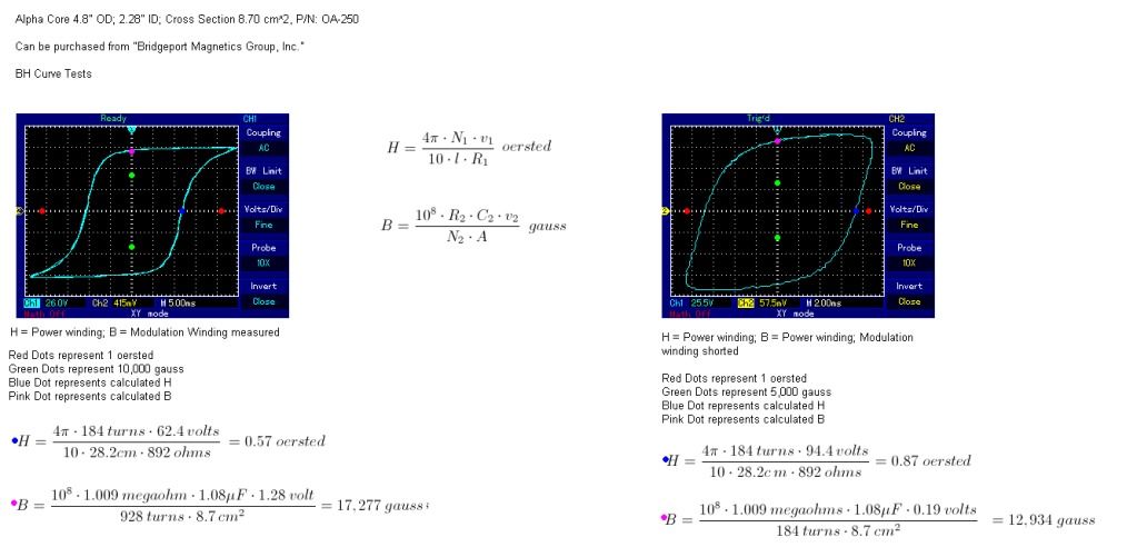
    • BH Curves

      I did some BH curve tests on my magamp core material. The screenshot on the left is measuring the magnetizing force, H, produced by one of the 184 turn power windings and is measuring the flux density, B, from the control winding.

      The screenshot on the right is measuring the magnetizing force, H, produced by one of the 184 turn power windings and is measuring the flux density at the other 184 turn power winding, this with the control winding shorted out in order to make this possible.

      I did both tests because it is awkward to try an do a BH curve test on a core that is intertwined with another magnetic circuit. I'm sure that between the two test, someone might get the gist of how this material behaves.


      Dave
      Last edited by Web000x; 09-21-2012, 11:19 PM.

      Comment


      • Foreword:Movement of Energy in Relation to AC:Action of Resistance & Negative Resistance:
        Last edited by garrettm4; 09-22-2012, 05:55 AM.

        Comment


        • A Proposed Mechanism for the Convergence of External Energy into a Parametric Device:external energy
          Last edited by garrettm4; 09-23-2012, 02:49 PM.

          Comment


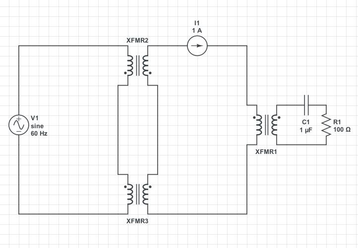
          • Dave, based on your comments and reading the web page about building a mag amp from radio shack parts, I was thinking you might be able to build a similar circuit with series transformers as outlined above. I think you were suggesting this in a previous post. Do you think this would work? If so, there'd be no need to wind any coils, you'd just need to make sure you had large enough transformers and that it was biased properly. Some of the component values listed above would most likely need to be adjusted.

            Comment


            • Originally posted by skaght View Post


              Dave, based on your comments and reading the web page about building a mag amp from radio shack parts, I was thinking you might be able to build a similar circuit with series transformers as outlined above. I think you were suggesting this in a previous post. Do you think this would work? If so, there'd be no need to wind any coils, you'd just need to make sure you had large enough transformers and that it was biased properly. Some of the component values listed above would most likely need to be adjusted.
              You need to take the constant current side of either XFMR2 or XFMR3 and reverse the leads. This way no EMF is induced into the constant current circuit from the modulation circuit. If you apply an EMF to the modulation side of the XFMRs, you should have approximately zero volts reading across the two power windings because the EMFs will cancel.

              If you don't get a very large inductance change on the power winding side from from passing current thru the control winding, the transformers might not work. I have measured my inductance change to be from 140 mH to 14 mH.

              Good Luck,

              Dave

              Comment


              • Hey All,

                I hate to be to be the boy who cried wolf AGAIN , but I think that I made a flaw in my measurements. For what I thought at the time was a good idea for the sake of simplicity was to measure the modulation winding losses by using i^2*R. i^2*R is for heat losses in the wire and does not reflect hysteresis losses. More investigation shows that there is a proportional energy loss in the hysteresis of the magamp material as there is a 'power gain' in the constant current circuit. I hadn't really taken this into account because the power windings are magnetically opposing the control winding which would cancel out any conventional energy transfer from the modulation winding to the control winding. I normally would have really investigated the circuit before I said anything, especially since the last incident, but this was the circuit that Eric told me to try so I had a bit more confidence in believing what I thought I was seeing. I just wanted to see others try to replicate it to see if the same results would be attained.

                My apologies to all.

                I'll keep trying.

                Dave

                Comment


                • Thermal Losses

                  Dave,

                  "I^2 * r" ISN'T just the "copper" loss it takes into account the hysteresis or "iron" losses AS WELL! Hysteresis is the effective EQUIVALENT of a PARALLEL connected ohmic resistance for ANY storage element be it a capacitor or inductor. Furthermore, ALL thermal losses are seen as an OHMIC resistance. This is why the copper AND the iron of a transformer BOTH heat up independently. Remember E * I = -P, for there to be power "dissipated" voltage and current have to be in phase - this is why all thermal losses APPEAR to be ohmic resistances. Further, the iron loss is composed of multiple factors not solely the hysteresis loss. Hysteresis in modern literature is considered as having two terms, one that is independent of applied frequency (the "static hysteresis loss" - losses do increase with greater frequency BUT the magnitude of the loss per cycle stays the same) and a second term related to frequency ("excess hysteresis loss" - magnitude of loss per cycle increases with increasing frequency), if I get some more free time I will post the expressions showing this. The Eddy Current losses, yet another constituent of the total iron losses, is directly related to frequency and maximum flux density. Other forms of resistive losses are seen as "radio waves" emitted due to RADIATION RESISTANCE which notably has to do with the characteristic impedance of a transmission line and is tightly related to the distance between the send and return wires and the frequency of operation.

                  Remember, you only have two quantities of "power" - what the watt meter says and what the VAR meter says. THESE two readings tell you EVERYTHING about the flow of energy in a circuit. The watt reading is the energy leaving (the source to a sink) the VAR reading is the energy that is circulating (between the source and the load). There need be no confusion, if you examine where the energy is actually going and what it is doing at that point. Also, the COP (coefficient of performance) is a great metric to use when talking about over-unity devices. Take the resistive load energy of the output divided by the effective resistive load seen on the input (in watts) and there's your Active Power COP (watt_out / watt_in). If you want to take into account the TOTAL "effective" energy flow, from input to output, you can find the Vector Power of the output and then divide this by the vector power measured on the input. This metric (VA_out / VA_in) gives you an interesting COP showing the effective flow of energy at the two points. This method of analysis might help in examining whats actually going on with the always mysterious quantity of "energy" we are so desperately trying to get more out than input.

                  To find the EFFECTIVE ohimic resistance (the sum of ALL ohmic losses) in your electrical network, R_eff, just use the AC form of Ohms law on the direct measurements you took from the circuit and use the cos and sin of the phase angle to break out the resistive and reactive terms. If the waveform is distorted then use an oscilloscope to find the peek values and then break down all the harmonics into their designated magnitude and frequency then apply the AC ohms law to each harmonic then combine them with the "sum of the squares" law (Sqrt(R_fundamenal^2 + R_3rd^2 + R_5th^2)) to to find the effective resistance more accurately.

                  *One more thing, a parametric transformer CAN transfer energy from the control winding TO the "POWER" winding - IF this is what you are concerned about with your setup. This mode of operation is how ALL the other people do it in the industry, don't fool yourself into thinking that this is an unused technology - its used ALL the time in telecom and radio. However, they don't APPLY the technology in a way that can operate in over-unity output. The changing of a parameter, say the inductance, at two times the output frequency can allow for a form of ORTHOGONAL mutual near-field coupling. Read "The Parametric Transformer" by E.S. Tez for more on this method of operation - the entire ~700pg thesis is dedicated to conventional 1:>1 output configurations using parametric variation.

                  Hope that helps, and keep up the good work.

                  Garrett M
                  Last edited by garrettm4; 09-22-2012, 10:36 PM.

                  Comment


                  • TV-part III - YouTubeTV-part II - YouTube
                    I think you'll agree that these guys are researching and probing the same area. I often ponder as a COP>1machine has yet to make it out into the public domain on a large scale what sort of percentage of forum members are here with the sole intention of laying false or miss leading spoor, I also find it a bit dubious when another subject seems to be introduced by a stranger to the thread (as Ive just done ) dont you? However it does seem to me that there is a vast ammount of research, written detail, maths, and video which has much in common with the areas of interest you are considering, That being the case I'll post these few links to the PDFs and video's
                    after all some one elses R&D freely given In the same area can save hours and hours of frustrating work and a great deal of money. That being the case I hope you find the time to a least scan the information here ...

                    CINATOTO Gebrakan Baru Situs Game Online Penggali Cuan Yang Kini Hadir Mewujudkan Imajinasi Dan Harapan Ketika Dicurangi Bandar atau Sistem.

                    TransVerter / Part 1 - YouTube (note there are 60 odd video's in this series)
                    TV-part I - YouTubeWorld's 10 most expensive energy projects - #9 - GLNG - $30 billion (2) - CNNMoney
                    Last edited by Duncan; 09-22-2012, 06:48 PM.
                    Whatever you can do,or dream you can,begin it.Boldness has genius,power and magic in it.Begin it now.

                    Comment


                    • Hi Duncan,

                      Thanks for posting. I watched the Transverter III video but I honestly couldnt see the relation to the PP18. The video seemed to mostly cover the diode plug, which seemed to be a novel way of collecting the output of a transformer into caps, and then switching the charged caps to a secondary circuit. I didnt seem to see any parameter variation there. If you are seeing something I am not, please correct me.

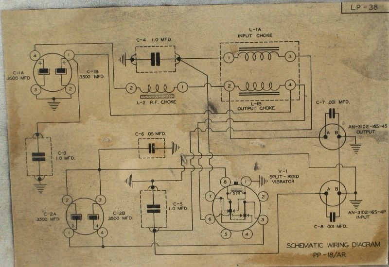
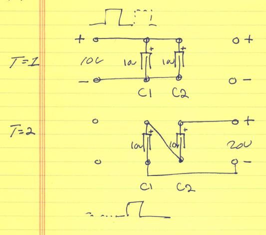
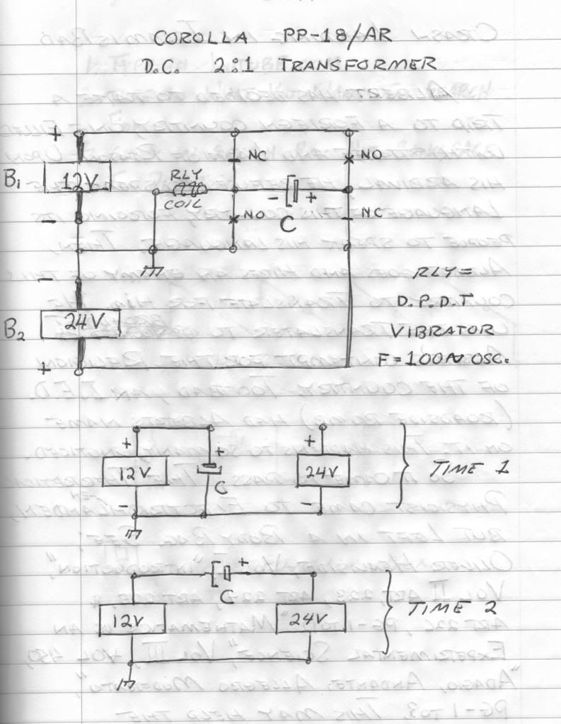
                      I attached a clearer schematic of the one you previously posted, as well as a few hand drawn notes by Eric of a much simplified idea of what is happening in the PP18.

                      The Rotoverter seems interesting, maybe you could perhaps describe in more detail how it properly functions. I have heard it referred to as a rotary version of a Magamp before.

                      Regards,

                      John


                      Please help support my indiegogo campaign: Cosmic Induction Generator

                      Comment


                      • Hi Dave,

                        I suggest you go get a couple of those kill-a-watt meters and put an end to your questions.

                        I'm only interested right now in doing a small scale replication with a single 9V battery powering the whole thing (don't want to spend lots of money on something that isn't proven on a smaller scale).

                        There is no reason this won't work on a small scale which will be a lot cheaper to tweak also. The power can be easily measured if the input & output are properly handled (with a large enough Capacitor to smooth out variations, you can get voltages and currents close to constant).

                        Also, on a small pulse DC core, you can change frequencies & duty cycle easily and I believe keeping the pulsing unidirectional and not AC, core losses can be reduced.

                        Thanks for the update Dave!

                        God Bless

                        Comment


                        • Mag amp

                          You can do essentially what Dave suggested previously with radio shack transformers.


                          I purchased two 2 amp 25 volt center tapped radio shack transformers and wired them up so the voltage across the secondaries cancelled. Then I used rectified ac to a capacitor as a control current. The change in inductance with the control current was huge. Inductance on primary measured .2 H with no control current, and over 20 H with ~.1 amp control current through the secondary. This setup is the real deal for parameter variation.

                          I did get an output voltage through the output transformer, but the power was definitely not impressive with my system. It's an easy setup to play with parameter variation, so I appreciate the post, even if the overunity claim was a mistake. There are oodles of variations that can be done, so the system may still yield interesting results if optimized.
                          Last edited by skaght; 09-23-2012, 03:31 AM.

                          Comment


                          • Garrett,

                            Thanks for your explanation. I really inherently knew all of this, but got caught up in the idea of using lumped constants.

                            My sincerest apologies for getting anybody's hopes up again. I still think this is the way to go, just a different variation.

                            @ Skaght,

                            Make sure you are using DC current in the control winding for your measurements. Sorry if my explanation was short on magamps, just figured that there was a common understanding on this thread.

                            Dave
                            Last edited by Web000x; 09-23-2012, 05:22 AM.

                            Comment


                            • The importance of parametric variation publicised in 1951.

                              Variation of parameters makes it into Hollywood history too. From the original 'The Day The World Stood Still', 1951, searching for a new energy source:

                              BARNHARDT
                              (slowly, thoughtfully)
                              Yes -- that will reproduce the first-
                              order terms. But what about the effect
                              of the other terms?

                              KLAATU
                              Almost negligible... With variation
                              of parameters, this is the answer.

                              BARNHARDT
                              How can you be so sure? Have you
                              tested this theory?

                              KLAATU
                              (with a slight smile)
                              I find it works well enough to get
                              me from one planet to another.

                              Professor Barnhardt (the smartest man in the world) was played by Sam Jaffe, who also held a B.Sc. in Engineering and was dean of mathematics at the Bronx Cultural Institute.

                              Comment


                              • Originally posted by Web000x View Post
                                Garrett,
                                @ Skaght,

                                Make sure you are using DC current in the control winding for your measurements. Sorry if my explanation was short on magamps, just figured that there was a common understanding on this thread.

                                Dave
                                I used the same style control current you previously described, rectified AC to a capacitor. There might be some ripple in my control current, but it is DC not AC.

                                S

                                Comment

                                Working...
                                X