Announcement

Collapse
No announcement yet.

Eric P. Dollard

Collapse
This topic is closed.
X
This is a sticky topic.
X
X
 
  • Filter
  • Time
  • Show
Clear All
new posts

  • jpolakow
    replied
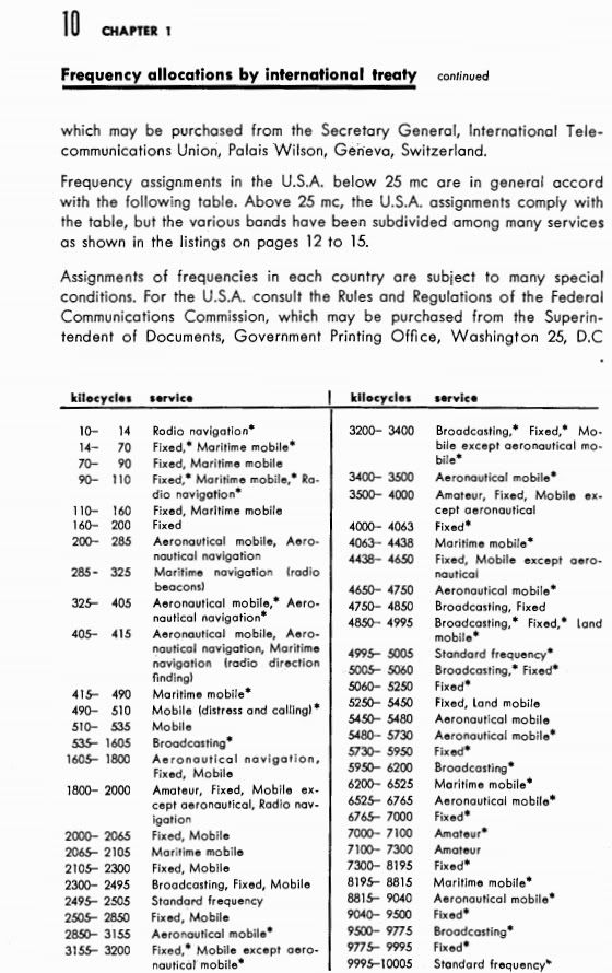
    This is the international frequency allocations. I was told by someone in the know that the bands marked "Fixed" (with nothing following) are no longer in use and would be perfect for experimenting on, but not deliberately transmitting on. Self cancelling push-pull coils only.

    Leave a comment:


  • Lambda
    replied
    Originally posted by T-rex View Post
    Mike,
    The PRC-47 was received. There were some broken parts that were replaced. It seemingly works. It receives ok, tomorrow will test transmitting. Thank you for the gift.

    73 DE N6KPH
    Your welcome Eric, thank you for the education that I couldn't obtain anywhere else. Really appreciate you hanging in there and taking us under your wing. I'm a little disappointed that there were any broken parts at all, glad you had the parts and able to make repairs.. I emailed the seller back and forth for nearly a month beforehand and he assured me there is nothing wrong what so ever. There was only one other PRC-47 I could find online for sale, they could do a visual inspection only, and not able to test it in any way, and as you know thats a no-go for buying a rig like this! Please let me know if it transmitts at full power or if the tubes are soft. Perhaps I'll catch u on 40m someday. Hope you do your bidaily transmissions again!

    Regards,
    Mike

    73 DE WX9HV
    Last edited by Lambda; 05-28-2012, 10:04 PM.

    Leave a comment:


  • t-rex
    replied
    Originally posted by Lambda View Post
    Hi Eric,
    I'm very appreciative for all of the great information you have been posting lately, nearly ready to get back to work on all of this stuff, hopefully less than a week. I know you have been putting a vast amount of time into your writing as it takes me quite a while to digest everything, again thank you!

    For the secondary & extra coil, is there other coax that will work well, although it would be a compromise, as the RG-316 is quite expensive. I already have several rolls of RG-8 & RG-8/U (low loss for VHF/UHF) that are extra since installing my tower here, and I recall you preferred to have a hollow secondary. Also have ~1000' of Commscope quad-shielded RG-6 CATV cable (coax is labeled as PR2712 F6SSVV 7461614), but I don't believe that'd be suitable.

    Have you been back to John's in Morro Bay, there has been a PRC-47 waiting for you there since April 20th that I purchased on ebay. The previous owner I bought it from claims it is in full operating condition (stated it worked fine and he used it until the wind took his antenna down). John sent me pictures of it, it looks to be in good condition physically. I hope it get's you back on the air at full output power and perhaps I can work you someday on 40m CW.

    Cheers,
    Mike

    73 DE WX9HV
    Mike,
    The PRC-47 was received. There were some broken parts that were replaced. It seemingly works. It receives ok, tomorrow will test transmitting. Thank you for the gift.

    73 DE N6KPH

    Leave a comment:


  • t-rex
    replied


    Leave a comment:


  • dR-Green
    replied
    Originally posted by Nhopa View Post
    but I still don't know where to hook-up the large adjustable capacitor
    One plate connects to top of secondary, and the other plate connects to bottom of secondary.

    Leave a comment:


  • madhatter
    replied
    went on a little shopping spree yesterday and picked up a couple of each,
    OA4G, OA2, OD3, OA3, JAN 2050 & a 3C45.

    Eric, are the 866's X, AX etc. mercury rectifier tubes useful?
    Also it seems that the Ukraine has an abundance of Mil-spec tubes for sale.

    Leave a comment:


  • jake
    replied
    Originally posted by Nhopa View Post
    Thank you jake, this will work, but I still don't know where to hook-up the large adjustable capacitor and should the 1/4" dia copper end ring tied to the upper end of the secondary coil. The difference in reading is about 400 Kc.
    Yes. The 1/4" copper ring needs to be connected to the top of the secondary. It essentially becomes the final turn of the secondary.

    Do not know about the neutralizing condenser. I was under the impression that the secondary served as both inductor and condenser.

    When u add the primary with capacitor it will drop the frequency of the primary/secondary setup. It will get you close to your calculated freq. At that point you would add the extra coil. Then your beating me cuz I ain't there yet.

    Good luck

    Leave a comment:


  • t-rex
    replied
    Secondary Tuning

    The oscillators I used were large Navy exciters but a solid state version may need more turns of finer wire like #22 and 6 turns. The copper end rings are the capacitor to start with. The secondary high lead connects to the bottom ring and the neutral lead connects to the top ring. A sheet of glass can separate the two, sandwiched between top and bottom rings.

    73 DE N6KPH

    Leave a comment:


  • OrionLightShip
    replied
    Avramenko Patent

    Eric,

    here is Avramenko patent on one wire transmission of power using displacement current.

    he is using a parameter variation, the details of which elude me; but I've yet to print this out and really study it. I've only read through it once late last night. hopefully, you will figure it out.

    Orion

    Leave a comment:


  • Nhopa
    replied
    Thank you jake, this will work, but I still don't know where to hook-up the large adjustable capacitor and should the 1/4" dia copper end ring tied to the upper end of the secondary coil. The difference in reading is about 400 Kc.

    Leave a comment:


  • jake
    replied
    Originally posted by Nhopa View Post
    Well, I tried to connect the Function Generator output to it's own ground, as shown in post #181 of 4/9/12, but as expected this kills the signal. So what is the correct hook-up?
    I think it should look like this. I tilted the one loop test coil a little bit so you can see the connections better but it should be orientated like the secondary.
    Attached Files

    Leave a comment:


  • Nhopa
    replied
    Testing

    Originally posted by Nhopa View Post
    Hi Eric:
    Also I will connect the Function Generator + and - together as shown in the posting...
    Well, I tried to connect the Function Generator output to it's own ground, as shown in post #181 of 4/9/12, but as expected this kills the signal. So what is the correct hook-up?

    Leave a comment:


  • madhatter
    replied
    Originally posted by jake View Post
    The green discharges also show up in "Gray Tube" and plasma spark experiments. And is not copper related.

    I've been working with discharges for a while now. I ran into a road block when I could not find an affordable diode capable of withstanding the 1000A+ surge current and blocking 12kV. And it needs to be pretty fast as well.

    This brings up a good point, the circuits for this type of work will more than likely need to be analog, the digital transistorized 'quantum' components are not going to perform or behave in the desired manner.

    the downside is that analog components and power sources are expensive and getting harder to get daily. I'd like to say it's the march of progress and the obsolete tech is inferior, in actuality the analog components are superior and behave in all sorts of interesting manners. it would seem then that's its a more orchestrated thing.

    Leave a comment:


  • Nhopa
    replied
    Tuning of secondary coil

    Originally posted by T-rex View Post
    ..... Finally, the secondary is made to be operated with a large external tuning condenser such as 2 six inch disks with variable spacing, or a large transmitting neutralizing condenser.
    Hi Eric:
    I will redo the testing as per you instruction. What I did so far was based on the procedures described in post #181 of 4/9/12. For the "Tuning setup - secondary coil" I did not notice any tuning condenser, so where do I connect it? Also I will connect the Function Generator + and - together as shown in the posting and connect the negative of the "Field intensity meter" to the ground plane. Also, is the secondary's end ring connected to the top of the secondary coil for this test?

    Leave a comment:


  • Nhopa
    replied
    Oa4g

    The OA4G is available from Ebay anywhere from $10 to $20 each plus shipping.

    Leave a comment:

Working...
X