Announcement

Collapse
No announcement yet.

Eric P. Dollard

Collapse
This topic is closed.
X
This is a sticky topic.
X
X
 
  • Filter
  • Time
  • Show
Clear All
new posts

  • madhatter
    replied
    Originally posted by lamare View Post
    However, the resulting wave that is being transmitted under these conditions does not have a magnetic component and that is the part we have trouble describing, because for waves to be able to propagate you do need a pair of two conjugate energies.

    And rotational magnetism is not one of these at the fundamental level and we have no way yet to describe these, even though they are probably related to magnetism. With magnetism you have some kind of momentum that flows in circles. The momentum we are looking for is basically the same, only that it does not flow in circles and therefore is not properly described in our models.
    From what I can see within the mathematical models is that the propagation is not thru the medium of our dimensional space. This is the why of Pi/2 velocity, hertzian waves travel thru our dimensional space. It may be that in order to move thru 'ether' the B field is in conjugate to E field, in a stressed dielectric where the fields are all parallel then instead of propogating the field thru the ether it's a door into the dielectric, aka the scifi 'wormhole'. the hyperbolic graph tends towards an asymptote or singularity. If this is truely the case it highlights a few issues. You'll always need a pair of 'doors', much like in scifi stories of worm hole gates, you need the other gate to get where you're going. It also means that without the other receiver there is no wave to freely transmit within the ether to bounce off objects, don't stop the moon bounce project based on this assumption though.

    It's the mathematical models that are showing this, this is why the inter-winding capacitance and inductance are key and critical to proper tuning. at each point of the dot scalar field between windings there is a reciprocal gate/door and this is where the magic happens. Steinmetz covers this briefly in one of his books as a chain of condensers, reading thru and noting the equations one can see he was also referring to coils, the rare time he's not dealing with transmission lines. I do wish he had more to say, I get the feeling it was a round about way of publishing work he was to keep quiet about.

    There is also the frequency factor which is ignored other than skin effect and even then it's misunderstood, get to that in a moment, if you notice in coil calculations for mutual inductance and capacitance between windings there is a simplification to sheet and field and this completely ignores the true relations of what is occurring. voltage potential between windings is far greater then the terminal ends and harmonics from the frequency and wave phase angle due to pitch and dia can be catastrophic to the coil, either very high losses or dielectric 'breakdown' which is exceedingly high potentials that become destructive.

    it's that phenomenon that is exploited and controlled. Skin effect and resistance to the conjugate wave is frequency dependent and not entirely logarithmic but seems to have two curves. if the depth of the wire is too close to the skin depth for that frequency the induced thermal gradient will destroy the conductor, other than a weight penalty a solid vs hollow wire for HF is the same. Now I not touching on the surface area or circumference that factors into inductance and capacitance.

    taking a simple example to highlight the parameters, two cylinders that are axial to each other and separated by a distance. the dia of each cylinder needs to be calculated for a given frequency and current and the distance between them. these ratios will effect the inductance and capacitance impedance which will effect the resonant point, a change in the spacing between cylinders will change the capacitance to greater extent then the inductance, whereas a change in the cylinder dia will effect the inductance greater then the capacitance. both of which will effect the resonant point and phase angle of the current to voltage. a greater change to phase angle in the coil diameter, this parameter also effects the inductance and capacitance in about that order of magnitude. adding to the mix is weather there is a ground termination, open end or return end on the terminal as each has its own effect.

    It becomes clear that in transmission lines of two wires there is a massive amount of calculations needed to get the desired results with AC frequencies. a coil is so much more complex in terms of geometry and how the field of a dot scalar product is calculated. I'm not sure how many of those parameters hold true when the line is looped into coil or if there is a translation.

    The math is difficult because the math in the first place is an imaginary construct of a net physical phenomenon. There simply has been no real civilian movement in the area of research and applied mathematics to this area, yes a few have pushed forward and made insights and some gains, I think though that most people don't comprehend the enormity of work that still needs to be done, mathematical models need inventing to produce testable theories and avoid blind research. Tesla experimented a lot, however unlike Edison Tesla understood the need for a mathematical approach to research. Steinmetz welded a pen and intellect that thankfully put down volumes of work that applied engineering can start from, Kennelly utilized Steinmetz work greatly in his applied calculations as did many others each to there own extent.

    Leave a comment:


  • Web000x
    replied
    Originally posted by Kokomoj0 View Post
    Huh?

    How do we know for a "fact" that system was LMD?

    LMD to the best of my knowledge is highly speculative, so how can we presume its a fact?

    Now that antenna probly did nice telluric transmission but then so does california power and light @ 60 hz TEM.

    How do we get a log periodic design resonate at one freq anyway?
    All of the engineering formulas were given. You will know if you stop talking about it and go build it. You will have much more credibility in your arguments if you have DATA from actually trying.

    You will know it is LMD if the inverse square law of distance begins to break down.

    Leave a comment:


  • lamare
    replied
    Originally posted by garrettm4 View Post
    Forewarning, what you are about to read is HIGHLY theoretical and may contain numerous errors, read at your own risk.

    Lamare,

    I disagree with a few things you have written recently regarding the dielectric and magnetic propagations alongst a solenoid, with special reference and application to a Tesla Transformer. While at the moment, neither of us can empirically prove our “personal understandings” and undoubtedly, we will both think our own opinions and references are the most correct, I thought I would still give my opinion as to the discrepancies I feel are present in your descriptions.

    IMHO, you are missing the most important detail in Eric's post:

    Originally posted by T-rex View Post
    It is however that the JJ Thompson Longitudinal Dielectric Motions cannot have a periodic solution, there is one energy only, dielectric. This needs to be resolved.
    It is _that_ problem that I am talking about and trying to resolve...

    As far as I can tell, ALL theories considering the magnetic field a fundamental property of the aether and consider it to be required for longitudinal wave propagations are flawed.

    I went into this a few days ago:


    Originally posted by T-rex View Post
    (6) L/K = C/M
    The T.E.M. component vanishes and the "Poynting Vectors" cancel out. The resistance of the coil also cancels out giving rise to a very great magnification factor, as well as a pure longitudinal wave, a "Tesla Coil".
    Originally posted by garrettm4 View Post
    Well sir, it would seem the "magic" happens when the QUOTIENT of the REACTANCES (from L & K) EQUAL the QUOTIENT of the SUSCEPTANCES (from C & M). This is quite PROFOUND (much meditation needs to be done on this concept). If you really look at what’s going on here WE NEED MR MAGNETISM because without him we can't make the REQUIRED situation TRUE, if we want to listen to Mr. Dollard, we have to actually contemplate what he has given us. To me it would seem magnetism is NOT the GREAT EVIL that everyone makes it out to be. What we want to do is CANCEL (or create a zero-vector of) the TEM portion of the ELECTRIC FIELD. If the Electric Field is the product of phi the magnetic and psi the dielectric, it would seem we can get ATLEAST TWO different MODES or PORTIONS of the Electric Field. What I find the most interesting is that in the LONGITUDINAL MAGNETO-DIELECTRIC MODE, we have the Electric Field, the Dielectric Field and the Magnetic Field ALL ON THE SAME AXIS (in the TEM case all three are on different axes). This may very well be the reason we only need to use one wire.

    I don't think we need any smoke or mirrors to understand the Longitudinal flow of energy. M and K are transfer coefficients (longitudinal) L and C are storage coefficients (transverse), its that simple. If L & K are seen as reactances and C & M are suceptances then a zero-vector sum of the reactances is a form of series resonance. Correspondingly the zero-vector sum of the suceptances is a form of parallel resonance. IF BOTH THE PARALLEL AND SERIES RESONANCES ARE EQUAL WE HAVE NO TRANSVERSE ELECTRO-MAGNETIC ENERGY, this is the "QUADRA-POLAR RESONANCE" (or so I believe it to be). The two counter rotating Poynting vectors create a ZERO-VECTOR, in this condition the MK portion is now free of the transverse wave interaction, the wave factor gamma has zero transverse component.

    The electric field does not have a TEM portion. You have the electric or dielectric field E and the magnetic field B, H or M.

    When you cancel the TEM component, you ARE cancelling the magnetic component. And _that_ is exactly what is so interesting about a coil. You _can_ cancel the magnetic field with it, under certain conditions. So, these theories can give you the conditions how to create your longitudinal wave.

    However, the resulting wave that is being transmitted under these conditions does not have a magnetic component and that is the part we have trouble describing, because for waves to be able to propagate you do need a pair of two conjugate energies.

    And rotational magnetism is not one of these at the fundamental level and we have no way yet to describe these, even though they are probably related to magnetism. With magnetism you have some kind of momentum that flows in circles. The momentum we are looking for is basically the same, only that it does not flow in circles and therefore is not properly described in our models.

    Leave a comment:


  • lamare
    replied
    Originally posted by Kokomoj0 View Post
    do you have a "working" demonstration of this?
    I am working on it:


    what exactly is "longitudinal resonance" as you are using it here? what is the media for this resonance exactly?

    How does dielectricity move without forming current?

    How does a current form without an associated magnetic field?

    Longitudinal resonance is a form of energy that is electrostatic (or dieletric) in nature. It is associated with a translational movement of the aether, while magnetism is associated with a rotational movement of the aether.

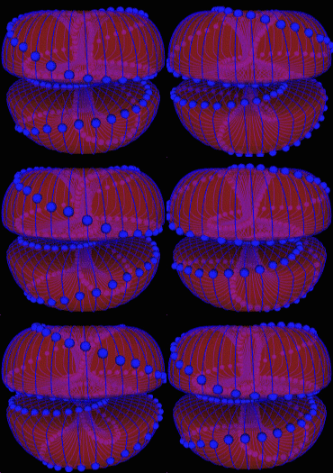
    Current is associated with the movement of particles, which are itself some kind of localized electromagnetic waves, that may look something like this:


    However, the aether itself can also flow, which is what it does all the time. Like the vortex/spiral like movements that enable particles to exist.

    So, dielectric waves can move without the need for particles to move around, because it involves movements of the aether itself. And that flow, which is NOT a "mass" or "particle" based current, can flow without an associated magnetic field.

    And that is what is missing in our current theories.


    That is not going faster than the speed of light but only having another path to follow by mutual inductance conductance insert whatever.
    The end result is that the wave propagates faster than the speed of light, exactly because the stuff that moves moves in a straight line, instead of in a spiral. Imagine the difference between a drunk bicycle rider and one that rides in a straight line. The drunk driver does not cover as much distance effectively, because he takes all these detours.

    And that is what light and particles do, which is why they move slower than the sober longitudinal dielectric wave.

    Interestingly, Wheatstone already measured the propagation speed of electrostatic waves along a wire back in 1834:


    This estimated velocity is on the supposition that the electricity passes from one end of the wire to the other: if, however, the two fluids in one theory, or the disturbances of equilibrium in the other, travel simultaneously from the two ends of the wire, the two external sparks will keep their relative positions, the middle one will be alone deflected, and the velocity measured will be only half that in the former case, viz. 288,000 miles in a second.
    That is 288,000/186,282 = 1.54 times the speed of light in vacuum. Damn close to the theoretical pi/2 or 1.57..

    Leave a comment:


  • Kokomoj0
    replied
    Originally posted by Web000x View Post
    You should really read "The Camp David Antenna" post by T-Rex for a second time providing that you actually read it the first go around. He is describing an ALEXANDERSON NETWORK based on a log-periodic design. He never claims that the TMT had anything to do with that particular antenna.

    By the way, the C.E.R.N. faster than light experiments didn't make you question the Theory of Relativity?

    Dave
    There is a much better experiment than that actually correcting the morley michelson interferometer tests that were done by them that makes one question the theory of relativity, however that does not at the same time magically validate LMD.

    Well maybe this is QST antenna design 101 thread, my mistake, my bad, I thought were all here to get demystified and get a clue on how to build a functional TMT from the presumed resident expert who talks about going backwards in time.

    That doesnt make you question LMD?

    Leave a comment:


  • madhatter
    replied
    Garrett, that's about the sum of it. I'm a bit tired so I haven't cross checked it with a fine comb but here's some supportive text by Steinmetz

    -perhaps with the only exception of
    low-resistance circuits containing large magnetic reactance,
    and large condensance in series with each other, so as to
    produce resonance effects of these higher harmonics.

    Page 10 of AC phenomena.

    The Radio engineers book is a decent read however I found it lacking in sufficient mathematical detail of Kennly and Steinmetz. To many one size fits all charts and quick look ups, fine for broad tuning of known variables but not helpful for this new type of design.

    coil inductance is usually treated as sheet value which simplifies greatly whats occurring.Thankfully Steinmetz gets right into the meat and potatoes of series capacitance and inductance of transmission lines, the tasking part is going thru the books 'thousands of pages' as we know and gleaning out the needed calculations and relations.

    Leave a comment:


  • garrettm4
    replied
    T-Rex Re-post

    This "transmission" by Mr. Dollard (originally two parts on the moon bounce thread) is one of the MOST IMPORTANT regarding the analysis of the Tesla Transformer (or ANY coil). I though it appropriate to re-post it here on the new thread for everyone's convenience:

    When considering waves on coiled windings, leave out the electrons, let us forget them once and for all. They are for electronic devices (RG) NOT for electrical devices (LC). Forget the electrons, forget it!

    It is generally considered that any wave must consist of a conjugate pair of energies, magnetic and dielectric let's say. Only then an interaction between time and space is possible. As I have shown recently it is through the union of a conjugate pair (L and C) that the dimension of time is produced. The propagation constant is then equal to:

    (1) Negative Gamma Square

    Having a pair of imaginary roots, plus j Gamma and minus j Gamma

    It is however that the JJ Thompson Longitudinal Dielectric Motions cannot have a periodic solution, there is one energy only, dielectric. This needs to be resolved.

    There are four distinct forms of energy stored in a winding,
    Magnetic Pair:

    L, Leakage Inductance, Henry
    M, Mutual Inductance, per Henry

    Dielectric Pair:

    C, Leakage Capacitance, Farad
    K, Mutual Capacitance, per Farad

    The Magnetic Distribution along the coil axis is given by

    (2) Epsilon to the square root of LM power. It is an exponential curve along the axis.

    The Dielectric Distribution along the coil axis is given by

    (3) Epsilon to the square root of CK power. It too is an exponential curve along the axis.

    LM an CK are time scalars hence it can be seen that these initial distributions at t = 0 give rise to complex energy exchanges because of the exponential space distributions. We have now a fourth order differential in space and time. Alice lands in Wonderland. Forget Maxwell, forget the Corums, dead ends, forget them once and for all!!

    Continuing with the four energy co-efficients:

    LC, this gives the space scalar frequencies of oscillation, having no distribution in space, only in time (dot product)

    MK, this gives the "Tesla Vector" normal to the coil windings, a counter-velocity in per centimeters per second. (axial product)

    Also,

    L/K this gives the clockwise "Poynting Vector" around the circumference of the coil windings, a velocity in centimeters per second (cross product)

    C/M, this gives the counter-clockwise "Poynting Vector" around the circumference of the coil windings, a velocity in centimeters per second (cross product)

    (4) Hence (LC + MK(k^2)) + k(L/K - C/M)

    (5) a +kb

    The Heaviside relation for the dimension of space. For the condition of balance,

    (6) L/K = C/M

    The T.E.M. component vanishes and the "Poynting Vectors" cancel out. The resistance of the coil also cancels out giving rise to a very great magnification factor, as well as a pure longitudinal wave, a "Tesla Coil".

    Forget the Corums, the Bewelly-Dollard Theory has made them obsolete. Also it is my own belief that we have outgrown Maxwell. The path started by Tesla, Through Steinmetz and Alexanderson, to L.V. Bewelly has taken us far beyond the primordial physics interpretation of J.C. Maxwell. Leyden Jars and scales have grown to giant substation transformers and high speed oscilloscopes. We are entering a brave new world of electricity, electricity without electrons.
    Garrett M
    Last edited by garrettm4; 04-03-2012, 05:23 AM.

    Leave a comment:


  • Kokomoj0
    replied
    Originally posted by Web000x View Post
    All I am saying is that the Bolinas Antenna is not the TMT. Yes, it will have similar operating principles when in the LMD wave resonant condition. All Eric is pointing out is another way to achieve LMD transmission via a different style antenna which happens to be a broadband T.E.M. compatible antenna as well as a single frequency L.M.D. compatible antenna.
    Huh?

    How do we know for a "fact" that system was LMD?

    LMD to the best of my knowledge is highly speculative, so how can we presume its a fact?

    Now that antenna probly did nice telluric transmission but then so does california power and light @ 60 hz TEM.

    How do we get a log periodic design resonate at one freq anyway?

    Leave a comment:


  • garrettm4
    replied
    Engended Fields about a Solenoid with respect to Longitudinal and Transvers Relations

    Forewarning, what you are about to read is HIGHLY theoretical and may contain numerous errors, read at your own risk.

    Lamare,

    I disagree with a few things you have written recently regarding the dielectric and magnetic propagations alongst a solenoid, with special reference and application to a Tesla Transformer. While at the moment, neither of us can empirically prove our “personal understandings” and undoubtedly, we will both think our own opinions and references are the most correct, I thought I would still give my opinion as to the discrepancies I feel are present in your descriptions.

    Problem #1:

    Since the longitudinal wave travels along the length of the coil, it does not "see" the inductance of the windings. It propagates from one winding to the next by means of the tiny capacitors that exist between the coil wires.
    MK; BOTH of the mutual inductions of the dielectric and MAGNEITIC fields travel normal to the wire or in-between the turns of the solenoid, this is seen as the length or height of the coil depending upon how you look at it. The individual self-capacities (C_s) as seen between any two turns, add to become the mutual capacity K, as seen from end-to-end of the coil. What you have avoided in bringing up is the MUTUAL INDUCTION of EACH TURN from the MAGNETIC FIELD, or MUTUAL INDUCTANCE M. I can’t quite grasp your phobia of the magnetic field and your never-ending efforts to avoid its calculation. It will always have some level of significance whether we want it to or not, so it’s best to not avoid it, and instead just accept it and attempt to gain new insight into its operations.

    Let’s go back and re-read what Mr. Dollard has written on this very subject:

    Continuing with the four energy co-efficients:

    LC, this gives the space scalar frequencies of oscillation, having no distribution in space, only in time (dot product)

    MK, this gives the "Tesla Vector" normal to the coil windings, a counter-velocity in per centimeters per second. (axial product)

    Also,

    L/K this gives the clockwise "Poynting Vector" around the circumference of the coil windings, a velocity in centimeters per second (cross product)

    C/M, this gives the counter-clockwise "Poynting Vector" around the circumference of the coil windings, a velocity in centimeters per second (cross product)
    It would seem Mr. Dollard takes into account BOTH of the magnetic inductions produced in the solenoids operation, not only that he also brings up the flow of energy of the Electric Field. My current, and lacking understanding, is that the TEM ELECTRIC FIELD is indeed the Poynting vector S. TO BE ABLE TO CANCEL THE TEM COMPONENT WE NEED BOTH INDUCTIONS OF THE MAGNETIC FIELD, this can be seen if you re-read the above quote very closely. WITHOUT THE (counter rotating) TE (C/M) & TM (L/K) WAVES "CANCELING" ONE ANOTHER (becoming a zero-vector), the counter rotating Poynting vectors of the Electric Field (the individual TEM components of the Electric Field), we will NEVER get PURE LONGITUDINAL OPERATION.

    Problem #2:

    And one of the first things you have to let go is the idea that the inductance or overall self capacitance of a coil is of any use. At frequencies above the self-resonance frequency of a coil, these are totally useless.
    There are FOUR co-efficients when dealing with a solenoid as seen in the afore mentioned Dollard quote.

    #1) The “self-capacity” of the solenoid is of a distributed nature and from end-to-end is similar to but NOT a normal self-capacity; it is a Mutual-Capacity (K) and can be seen as a TRANSFER COEFFIENT and constitutes a reactance, (in this circumstance it is a longitudinal flow of dielectric energy).

    #2) The “self-inductance” is also of a distributed nature and the COUPLING between turns causes a Mutual Magnetic Induction (M) or TRANSFER OF ENERGY between windings and constitutes a suceptance, (in this circumstance it is a longitudinal flow of magnetic energy).

    #3) The UNCOUPLED ENERGY IS THE LEAKAGE INDUCTANCE (L), this is a STORAGE COMPONENT and constitutes a reactance, (in this circumstance it is transverse flow of magnetic energy).

    #4) Finally we have the Leakage Capacitance (C) to ground, here the whole wire is seen as a “cylindrical capacitor plate” and the earth as the other “capacitor plate” this is seen as a STORAGE COMPONENT and constitutes a suceptance, (in this circumstance it is a transverse flow of dielectric energy).

    With that covered let’s take a look at another quote from Mr. Dollard:

    L/K = C/M

    The T.E.M. component vanishes and the "Poynting Vectors" cancel out. The resistance of the coil also cancels out giving rise to a very great magnification factor, as well as a pure longitudinal wave, a "Tesla Coil".
    Well sir, it would seem the "magic" happens when the QUOTIENT of the REACTANCES (from L & K) EQUAL the QUOTIENT of the SUSCEPTANCES (from C & M). This is quite PROFOUND (much meditation needs to be done on this concept). If you really look at what’s going on here WE NEED MR MAGNETISM because without him we can't make the REQUIRED situation TRUE, if we want to listen to Mr. Dollard, we have to actually contemplate what he has given us. To me it would seem magnetism is NOT the GREAT EVIL that everyone makes it out to be. What we want to do is CANCEL (or create a zero-vector of) the TEM portion of the ELECTRIC FIELD. If the Electric Field is the product of phi the magnetic and psi the dielectric, it would seem we can get ATLEAST TWO different MODES or PORTIONS of the Electric Field. What I find the most interesting is that in the LONGITUDINAL MAGNETO-DIELECTRIC MODE, we have the Electric Field, the Dielectric Field and the Magnetic Field ALL ON THE SAME AXIS (in the TEM case all three are on different axes). This may very well be the reason we only need to use one wire.

    I don't think we need any smoke or mirrors to understand the Longitudinal flow of energy. M and K are transfer coefficients (longitudinal) L and C are storage coefficients (transverse), its that simple. If L & K are seen as reactances and C & M are suceptances then a zero-vector sum of the reactances is a form of series resonance. Correspondingly the zero-vector sum of the suceptances is a form of parallel resonance. IF BOTH THE PARALLEL AND SERIES RESONANCES ARE EQUAL WE HAVE NO TRANSVERSE ELECTRO-MAGNETIC ENERGY, this is the "QUADRA-POLAR RESONANCE" (or so I believe it to be). The two counter rotating Poynting vectors create a ZERO-VECTOR, in this condition the MK portion is now free of the transverse wave interaction, the wave factor gamma has zero transverse component.

    We have journeyed long and hard through the "rabbit hole" and now find our selves in the center of the earth, a place few ever see and fewer live to tell the tale. Will we be able to make it back topside with our new-found insight?

    Once again, the contents of this post are highly theoretical and subject to error so don't take everything as being exact, instead think of it as an alternative view or possible solution.

    Garrett M
    Last edited by garrettm4; 04-04-2012, 12:51 AM.

    Leave a comment:


  • Web000x
    replied
    Originally posted by jake View Post
    Wait I thought the camp David antenna had a direct correlation to the TMT? In terms of each components function.
    All I am saying is that the Bolinas Antenna is not the TMT. Yes, it will have similar operating principles when in the LMD wave resonant condition. All Eric is pointing out is another way to achieve LMD transmission via a different style antenna which happens to be a broadband T.E.M. compatible antenna as well as a single frequency L.M.D. compatible antenna.

    Leave a comment:


  • jake
    replied
    Originally posted by Web000x View Post
    You should really read "The Camp David Antenna" post by T-Rex for a second time providing that you actually read it the first go around. He is describing an ALEXANDERSON NETWORK based on a log-periodic design. He never claims that the TMT had anything to do with that particular antenna.

    By the way, the C.E.R.N. faster than light experiments didn't make you question the Theory of Relativity?

    Dave
    Wait I thought the camp David antenna had a direct correlation to the TMT? In terms of each components function.

    Leave a comment:


  • Web000x
    replied
    Originally posted by Kokomoj0 View Post
    Now if you look above we have Dollard telling us to build a log periodic antenna as if that has anything what so ever to do with the TMT.

    Of course it would have worked good for tv and receiving hertzian waves.
    You should really read "The Camp David Antenna" post by T-Rex for a second time providing that you actually read it the first go around. He is describing an ALEXANDERSON NETWORK based on a log-periodic design. He never claims that the TMT had anything to do with that particular antenna.

    By the way, the C.E.R.N. faster than light experiments didn't make you question the Theory of Relativity?

    Dave
    Last edited by Web000x; 04-03-2012, 02:57 AM.

    Leave a comment:


  • Kokomoj0
    replied
    Originally posted by wyndbag View Post
    Ok so Kokomoj0 has profiled me and its probably true.... but just because my brain is a little on the soft side, I do have thoughts questions and possible ideas to float. Here is one I have not heard of yet but perhaps someone here has:

    it seems like a great deal of time and energy is spent building things that pretty much do what all the other coil builders are doing, some better than others of course, but pretty much the same.

    It seems to me that utilizing for instance single a high voltage power supply makes the whole process hit or miss. Why not utilize a regulated high voltage power supply off an old x-ray machine. That way the power can be tuned via the controls on the machine which typically controls the output as KV and MA. That way tuning can take place from the input as well as the output side. Anyone tried this?
    nope that was a shot over Dollards bow who appears to be starting to take this seriously into left field. Log periodic antennas for petes sake have nothing "directly" in common with TMT unless you want to say you can use math in both cases.

    Never in a million years did I think I would be forced to say something like that.

    Leave a comment:


  • madhatter
    replied
    Originally posted by wyndbag View Post
    Ok so Kokomoj0 has profiled me and its probably true.... but just because my brain is a little on the soft side, I do have thoughts questions and possible ideas to float. Here is one I have not heard of yet but perhaps someone here has:

    it seems like a great deal of time and energy is spent building things that pretty much do what all the other coil builders are doing, some better than others of course, but pretty much the same.

    It seems to me that utilizing for instance single a high voltage power supply makes the whole process hit or miss. Why not utilize a regulated high voltage power supply off an old x-ray machine. That way the power can be tuned via the controls on the machine which typically controls the output as KV and MA. That way tuning can take place from the input as well as the output side. Anyone tried this?
    Not sure about the power supply being a problem. the net result here is to duplicate the longitudinal wave of dielectric. With a network of working coils we could then transmit and receive between sets proving that C is not a limit.

    There is also the curious factor of reducing the magnetic field to where it is no longer an impedance in the circuit. When considering the finite velocity of propagation of the electric field, self-inductance thus is not wattless, but contains an energy component, and so can be represented by an impedance.

    in simple terms its rotating the vectors to where they are in parallel and then you'll have a wave propagation velocity that not only exceeds C but would not have the losses, leakages or impedance of current designs. That opens the door to many interesting things, "lightning in a bottle".

    Leave a comment:


  • wyndbag
    replied
    Ok so Kokomoj0 has profiled me and its probably true.... but just because my brain is a little on the soft side, I do have thoughts questions and possible ideas to float. Here is one I have not heard of yet but perhaps someone here has:

    it seems like a great deal of time and energy is spent building things that pretty much do what all the other coil builders are doing, some better than others of course, but pretty much the same.

    It seems to me that utilizing for instance single a high voltage power supply makes the whole process hit or miss. Why not utilize a regulated high voltage power supply off an old x-ray machine. That way the power can be tuned via the controls on the machine which typically controls the output as KV and MA. That way tuning can take place from the input as well as the output side. Anyone tried this?

    Leave a comment:

Working...
X