Announcement

Collapse
No announcement yet.

My Motors got me to Tap into Radiant Energy

Collapse
X
 
  • Filter
  • Time
  • Show
Clear All
new posts

  • Ufopolitics
    replied
    Hello Warren

    Originally posted by warrensk View Post
    Hello,

    thanks for the tip prochiro...I was under the impression that the latest circuit UFO posted was the one to work on...just thought of something i knew i read somewhere but wasnt sure where. (lots of pages on this forum)

    I will work on my circuit and make sure to do everything explained. I figured I could hook up a larger bank of batteries this way without interfering with the timer circuit. let me know if you think otherwise. I am a newbie with these circuits but i think this way works without the need of a voltage regulator.

    [ATTACH]12648[/ATTACH]

    As for the other antiphase PWM circuit....i will start working on that too. I will make sure to look back into this forum again and make sure i am up all caught up.

    Thanks again to all for the great help,

    Warren
    Hello Warren,

    First, You have to focus in just ONE development at a time...please!
    When You mentioned "Anti-Phase" you trigger Prochiro to direct you to Mad Scientist Circuit where I was asking Him to make Us an Anti-Phase...and He did it greatly...BUT they are TWO DIFFERENT DEALS here...Mad Scientis is based on another IC...not the 555...LM339 I believe...and I have not had the time to make it, even though I have all components to do it...

    Yes, the Circuit I have been working on ALL this Time...is the one above...the one I displayed with the 555 Timer...N-Channel.

    However, later on I developed an Anti-Phase one....based on TWO 555's where One is Master...the other one a Slave Mirror...but generating the opposed Phase at P-Channel FET'S...So I have TWO Controllers...However, the N-Channel is way more robust, since I have not been able to find the right P-Channel FET's that are compatible in RdsOn...and other spec's as the N-Channel FET's...they are weaker (P-Ch)

    So, to run Motors...I have been using this same old circuit...above.(555-N-Ch)

    Now, others here have gone to a Company that makes them...DY Electronics or something like...is all here guys...search,search...then keep searching...that is the MAIN KEY here...all has been displayed already.

    Now related to separate feeds for 12V and FET Switch...We have gone over that issue here many times...is ALSO HERE!...I have explained why, as also shown the simplest like two resistor, One Transistor (LM317) and a couple of Caps...that is it...You got a great V-Reg...that will go as high as 36V...and I have that incorporated to My 555 Oscillator N-Channel...works wonderful.

    Two separate feeds could develop in a disaster if FET's go bad and join Gate to Drain (and that is the way they normally say BYE)...However, Member Torpex have been doing it without problems...(that I know off)


    Regards


    Ufopolitics

    Leave a comment:


  • sawa25
    replied
    Originally posted by Ufopolitics View Post
    Hello and Welcome Sawa25!

    Check on pages ahead...there should be more Diagrams, as in this page...above is again the same circuit I am using...

    UFOPOLITICS PHOTO BUCKET LIBRARY

    As also Mr Patrick Kelly add me in his site...for both Threads...don't remember the Chapters where I am...later I will look it up.

    Regards

    Ufopolitics
    Thanks! photogallery make an impression.
    but which one the circuit (to try) where you deep in to water fluorescent lamp? want to start with it,or this is wrong first step?
    as for your Pulse Wave Modulator circuit-not sure- where to connect lamp
    and where to connect coil, and wether it is for that?(on PatricK site Chapter3 page 3-134 there is one with lamp similar to PWM,but differences confuse me,because i am much far from profi in this
    exuse for oftop: seems very important your remark, about lure RE: condition when it manifest itself(doing work) not the same that make it to begin, so we should tune the starting and continuating processes Probably because of this i don't know one, who get sucсess in replicating Don Smith(the most popular board of his devices), no way to tune for startup .(not sure i correct say in English what i want . )
    Last edited by sawa25; 12-20-2012, 05:11 PM.

    Leave a comment:


  • warrensk
    replied
    PWM circuit with load batteries separate?

    Hello,

    thanks for the tip prochiro...I was under the impression that the latest circuit UFO posted was the one to work on...just thought of something i knew i read somewhere but wasnt sure where. (lots of pages on this forum)

    I will work on my circuit and make sure to do everything explained. I figured I could hook up a larger bank of batteries this way without interfering with the timer circuit. let me know if you think otherwise. I am a newbie with these circuits but i think this way works without the need of a voltage regulator.

    PWMloadseperate.jpg

    As for the other antiphase PWM circuit....i will start working on that too. I will make sure to look back into this forum again and make sure i am up all caught up.

    Thanks again to all for the great help,

    Warren

    Leave a comment:


  • Ufopolitics
    replied
    Originally posted by warrensk View Post
    Thanks ufo,

    I was trying to look at a signal on my scope and couldnt get a good looking signal...probably because it was not grounded properly. I also noticed that the frequency would change with the capacitance i would add to the circuit by touching it with my hand. I build the circuit exactly as shown with one FET (irf740a)...

    I built the circuit on a circuit board and realized the frequency couldnt adjust far enough...I started switching out the capacitor on pins 2/6 for larger or smaller ones. Is there a way to adjust duty cycle and frequency separately?

    Also, is there a way to pulse 2 channels in anti phase (or 4 in sequence) and adjust for duty cycle and frequency for each channel? I want to see what happens when electricity is pulsed during the radiant spike so the 2 vectors will be going same direction instead of opposing like they are usually.

    Just uploaded some new videos

    Radiant Energy lights up neon - YouTube

    Radiant energy lights up neon purple experiment #2 - YouTube


    Watch and let me know what you think. I got my neon to light up strictly purple but couldnt replicate it again. I am only using 6 volts in these videos, thought the high voltage was impressive from only that small of a dc input.

    Thanks again for all the help!

    Warren
    Yes Warren,

    You've got Radiant Light on the second video...not on first one...Orange is predominating there too much. However you getting for too short times/pulses On...

    Watch my video below...so you get familiar with its looks and flickering behavior...according to pulsing.

    RADIANT ENERGIZED NEON - YouTube

    Still have to work on your oscillator circuit pulses...remember that Coil needs to be pulsed much higher peak voltages than 6 or 12V...but then you will need voltage regulators to separate switching FET's circuit from oscillator chip side...which is much lower than 24 or 36V...

    Regards


    Ufopolitics

    Leave a comment:


  • prochiro
    replied
    Warren
    Now that is the correct purple. Most have found that a voltage over 12 will do better. Enjoy the show.
    Dana

    Leave a comment:


  • prochiro
    replied
    Warren
    Now I am not picking on you but it is evident that you have not read the thread vary well at all. Mad Scientist has posted all the information and several circuit diagrams, one of which is just what you ask about two way pulsing. These are not just in one small area but over several pages. The final circuit you asked about is on page 12 at post 360. Please , as UFO has requested, read every item of this thread if you hope to catch up. Every page has an answer to something. Let me show you how it works. When a person reads a paragraph, gets to the end and does not have a 100% understanding of that paragraph, it is because he read over (ONE WORD) that he did not know all of the meanings and conditions of that (ONE WORD). Thus he learned nothing. Go to page 12 my dear friend and read.
    Dana

    Leave a comment:


  • warrensk
    replied
    Sensitive circuit?

    Thanks ufo,

    I was trying to look at a signal on my scope and couldnt get a good looking signal...probably because it was not grounded properly. I also noticed that the frequency would change with the capacitance i would add to the circuit by touching it with my hand. I build the circuit exactly as shown with one FET (irf740a)...

    I built the circuit on a circuit board and realized the frequency couldnt adjust far enough...I started switching out the capacitor on pins 2/6 for larger or smaller ones. Is there a way to adjust duty cycle and frequency separately?

    Also, is there a way to pulse 2 channels in anti phase (or 4 in sequence) and adjust for duty cycle and frequency for each channel? I want to see what happens when electricity is pulsed during the radiant spike so the 2 vectors will be going same direction instead of opposing like they are usually.

    Just uploaded some new videos

    Radiant Energy lights up neon - YouTube

    Radiant energy lights up neon purple experiment #2 - YouTube


    Watch and let me know what you think. I got my neon to light up strictly purple but couldnt replicate it again. I am only using 6 volts in these videos, thought the high voltage was impressive from only that small of a dc input.

    Thanks again for all the help!

    Warren

    Leave a comment:


  • Ufopolitics
    replied
    Hello and Welcome Sawa25

    Originally posted by sawa25 View Post
    Very interesting to read about ufo researchers, but unfortunately on the appropriate pages(where discussion have just started) are only text w/o any pics
    i have looked through dozens of posts with empty box where the pics must be.
    the last pics are ok.
    probably moderator delete older pics?
    Where to see circuits (may be on other web site)?
    Hello and Welcome Sawa25!

    When I first started this Thread, back in February of this year...I did not have Photobucket...therefore I used the server here to load my pic's...and space is limited, so I had to keep erasing to upload new pic's and files...

    Check on pages ahead...there should be more Diagrams, as in this page...above is again the same circuit I am using...

    UFOPOLITICS PHOTO BUCKET LIBRARY

    As also Mr Patrick Kelly add me in his site...for both Threads...don't remember the Chapters where I am...later I will look it up.

    Regards


    Ufopolitics

    Leave a comment:


  • Ufopolitics
    replied
    Nice BUT...

    Originally posted by warrensk View Post
    UFO pwm neon experiment - YouTube

    I havent mounted the FET on a heat sink yet....already blew one....the neon also blew up before the FET did....the neon seems to create lots of heat when it is more orange/reddish. Theres a little bit of purple in there but I probably dont have it set up the best right now. More to come....Thanks for all the great help guys!

    Warren
    Hello Warren,

    Great BUT...notice on video when you first start orange light comes out too strong...it should NOT be that way...you have some problems at the resistors (two) and the Potentiometer could be either not the right 250 KOhms...or have to adjust it to almost ZERO frequency at start.

    Normally there always would be a first flash out at start...but then it should go off completely...and zero on frequency meters...then the dialing should be VERY SLOW...Radiant higher percentages/orange very low to NONE... should manifest at VERY LOW Pulses...

    Remember Purple Light is Radiant...Hot is Orange...so that is your "Light Monitor" there...

    I tell you what I did:

    The two resistors that attach to POT, instead of using typical resistors...I used very small trimmers or very small potentiometers that could be regulated only with a small flat PLASTIC screw driver...NOW, the side that connects to Power Source Positive, no diodes, leg 4-8...be very careful adjusting it!...if you reduce resistance too low...you will definitively blow your Oscillator IC, so I recommend to adjust using a Meter hook to the two Trimmer terminals...NEVER BY EYES AND EARS!

    Also set main POT Wiper at the LOWEST STARTING FREQUENCY STAGE (MAX Resistance Value) to do this adjustments.

    I also used a VERNIER DIAL attached to POT shaft...this way you reduce the traveling when dialing by hand.

    Last thing...this circuit should be grounded to chassis...to avoid interference with your hands ground and POT Regulations that normally tends to jump up the frequency at contact...

    Vernier dialer's are isolated...but if using direct POT make sure the Knob is Plastic....You are dialing directly with your hands...NOT GOOD either!...This circuit is very sensitive.


    Regards and hoping to see that Radiant Beautiful light soon!


    Ufopolitics
    Last edited by Ufopolitics; 12-18-2012, 09:23 PM.

    Leave a comment:


  • sawa25
    replied
    ask for Advise

    Very interesting to read about ufo researchers, but unfortunately on the appropriate pages(where discussion have just started) are only text w/o any pics
    i have looked through dozens of posts with empty box where the pics must be.
    the last pics are ok.
    probably moderator delete older pics?
    Where to see circuits (may be on other web site)?
    Last edited by sawa25; 12-18-2012, 08:34 PM.

    Leave a comment:


  • warrensk
    replied
    UFO pwm neon experiment

    UFO pwm neon experiment - YouTube

    I havent mounted the FET on a heat sink yet....already blew one....the neon also blew up before the FET did....the neon seems to create lots of heat when it is more orange/reddish. Theres a little bit of purple in there but I probably dont have it set up the best right now. More to come....Thanks for all the great help guys!

    Warren

    Leave a comment:


  • JohnStone
    replied
    Regarding welders:
    Please note that the amperage of welders relates to the case of actual welding. This is while welding arc burning. i.e. 15V times 160A = 2400W. This is no normal constant voltage PSU and thus you are not allowed to multiply idle voltage with amperage in duty!
    If the idle voltage is i.e. 40V you can expect less amperage than: 2400W / 40V = 60A .
    This does not mean you can not use welders but you shall note that they are not constant voltage PSUs but contollable amperage (not necessarly constant). The voltage will rapidly go down to a balanced amp/volt ratio. This ratio will adapt constantly depending the load you apply to the prime mover.

    Non electonic welders have a air gap inside their core in order to perform like above. Those with a constant adjust wheel are able to modify this air gap mechanically. There you might have the chance to insert a iron sheet in the gap in order to make the transformer stiffer in order to hold voltage more like a normal transformer.
    Last edited by JohnStone; 12-18-2012, 03:10 PM.

    Leave a comment:


  • Lester444
    replied
    Originally posted by Ufopolitics View Post
    Related to Caps I have Two 22000 Uf rated at 85V/Surge at 95
    Or I could also have 10/1000 uf/100V
    Hello UFO,

    I have computed ripple voltage for you. Just a rough estimate because the load is a motor.

    At 50A the ripple voltage will be ~9.5Vp-p with 44,000uF (FWBR)
    At 50A the ripple voltage will be ~7.7Vp-p with 54,000uF (FWBR)

    I hope the motor won't mind having that much ripple at 120Hz. Yes those caps are being stressed out indeed. Please stay safe.


    @JohnStone,
    Thanks. The DC welders can be floated off ground although I do realize that's a safety hazard.
    I also see what you mean, FET supply coming off the mains. Roughly 150VDC or 300VDC depending on where you are. Definitely not for amateur experiments.

    Lester444

    Leave a comment:


  • warrensk
    replied
    Originally posted by Ufopolitics View Post
    Hello to ALL,

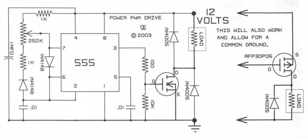
    I am presenting here the simplest PWM (Pulse Wave Modulator) and Motor Controller that you could build, it is based on the very cheap 555 Timer...and it could work "Safely"with up to 12 Volts...without the need of a Voltage Regulator.

    [IMG][/IMG]

    This is the circuit I have been using all along in My very First Thread, I just added an LM317 Voltage regulator that is posted in my other Thread, it consist of the Transistor LM317, a couple of Electrolytic Caps and a couple of resistors...and I did it in order to apply a Higher Input that ranges from 24V to 36 Volts...But the basic circuit is this one here.
    Timer works in the "Astable" Mode...rendering a very clean Square Wave...
    You will need this as a Controller to run from the very small Motors to the Bigger ones...so it is very practical...

    Also it will allow by just adding "Two Components" a Non Polarized Cap and a Diode...to make a SEPIC System that will control Input and Output from Machine Gates.

    I got this Circuit from: PROJECTS

    On:A Pulse Width Modulation Control

    I highly recommend this site for other great electronic free circuits as Switching Power Supplies and others...as Gary also sells parts there and the assembled circuits (for those that rather order them)...He is a very nice guy.

    I am not saying the other circuits are not good, on the contrary, the LM393 is a great circuit (Mad Scientist)...as it allows regulations of Duty Cycle and Frequencies...As also the great Modular Circuit designed by My Friend John Stone...However, they could become pretty complicated and all we are trying here is to Keep It as Simple as Possible...(note I did not write KISS... )

    To all the Members that have replicated my work:...I highly recommend to build this simple circuit...as it is the ONLY way you could see How My Machines Output True Radiant Energy Purple Plasma Sphere of Light...manifested at very low pulses...in the Electrodes of a 120 V Neon Bulb...


    ...and I know you will love HER...as SHE is the reason why we are getting all this "Phenomena" that many can not explain to be possible...then you all will understand better everything displayed here...as How I found HER originally...

    I believe it is a very lovely light you could not miss to see...


    Regards to all


    Ufopolitics
    Hello all,

    I am currently building this circuit and was wondering where to put a second potentiometer to control just the frequency.

    Also, I got an idea to do a 2-4 channel PWM that pulses in anti phase...So our hot pulse could come in right as the radiant spike comes in from the collapse of the previous pulse ...this could in turn add vectors together (both our hot and radiant going in same direction...) We could find the best duty cycle, then match it in frequency to get the most radiant energy out....I feel that if we add our hot pulses at the right time (same time as the radiant spike comes in) their vectors could add together...maybe resulting in a larger radiant spike. This is something I would like to test....adding minimal amount of hot electricity to swing radiant back and forth through the coil stronger and stronger....An arduino could be used to set up 4 PWM's all firing in sequence till it loops back around to the first FET...just an idea. let me know what you guys think.


    Something like this could offer much faster frequencies than the original circuit...

    Thanks,

    Warren
    Last edited by warrensk; 12-18-2012, 01:49 AM.

    Leave a comment:


  • Ufopolitics
    replied
    Thanks EWizard...

    Originally posted by ewizard View Post
    UFO, 60 Amp 1000 volt rectifier on eBay but it's from Miami, FL so maybe close to you? $7.43. Here: New Diode Bridge Rectifier Model KBPC6010 60A 1000V | eBay

    I see lots of 100 Amp rectifiers too on eBay most are 1600 volt but are mostly out of China and most are 3 phase but saw one which is single phase.

    Hello Ewizard,

    Thanks for your kind search...but I got the BR already...
    It is worth the Money...is a super duty one, very strong casing and I got its sink also.


    Regards


    Ufopolitics

    Leave a comment:

Working...
X