-
Last edited by JohnStone; 05-08-2014, 08:37 PM.Experts spend hours a day in order to question their doing while others stopped thinking feeling they were professionals. -
Thank you Cornboy
Thank you Cornboy.Originally posted by Cornboy 555 View Post
There was my dream to be involved in this field of research in the beginning of 90's of the last century. :-) But I had not had enough time to do something in that time. And before internet I did not know where to start, what to do, where could I find any guide.
And my English (my mother language is not English) also was much more worst then now. At least now I can read in English or can't
So, I am sorry if there are grammatical errors in my writing.
Regards:
Holbi "Knowledge is as good as it used."
Comment
-
Thank you JohnStone!
Thank you John!
Originally posted by JohnStone View PostI agree with you, and I do not expect the immediate measurement. Even the traditional hot electricity is measured by different indirect methods. The hot electricity measurement uses the magnetic side effect of running current. And it is all.Originally posted by JohnStone View Post
I am looking for a side effect of the radiant/cold electricity that can be used for the indirect measurement similar to the hot electricity.
If we would like to do some engineer job in this field (and not only speculations) we have to establish a law for this radiant/cold phenomena, and measure in the real world that: Is this law true or false?
Radiant energy or cold electricity looks like some kind of energy. If this type of flow is a kind of energy (and I am sure about it) we should measure some quantity and some quality of this flow.
Every energy flow can be characterized by its- direction;
- potential different;
- current (or flow or flux);
- waveform;
- wavelength;
- frequency;
- oscillation direction or oscillation type (transverse, longitudinal, screwed, spinning, vortex type etc. or all of these combination);
- amplitude;
- intensity;
- density
Every energy flow will move in a medium, so there should be:- popular medium for this type of flow (conduction) and
- avoided (not popular) medium for this type of flow (resistance).
In the case of "traditional electricity and magnetism" these quantity and quality well known and the relation between these quantity and quality was good established in the past (e.g. by J.C. Maxwell).
If we would like to move forward on the so called free energy research we should find some engineering method to measure different quantity and quality so called "radiant energy" flow.
I am convinced that the one of the basic barrier on this way is the lack of the exact measurement method for the "radiant energy" flow.
OK. I understand it.Originally posted by JohnStone View Post
We did some measurement with CFL bulb immediately, using photometry. We used a lux-meter application of an Android smart-phone and measured the illuminance of 15W CFL bulb connected to the 230 V AC main. (it was 54,000 lm/m2). Then with correcting frequency and duty cycle we set up the CFL connected to the cold electricity source to the too same illumination. The whole system consumed ~ 3.2 W in this case. Comparing consumed powers: 15W/3.2W = COP 4.7 for the too same effect, illuminate some light.
Relative measurement is also suitable.Originally posted by JohnStone View Post
Capturing and later converting cold electricity into the traditional hot electricity and to measure the collected amount of "charge", is also suitable.
I think we have to find some agreement on the issue: how to measure this phenomena - and it will be the real scientific start of this research field.
Regards:
Holbi "Knowledge is as good as it used."Comment
-
@John Stone
Good to see a post from you, as it has been a long time my friend since we have had your sage advice on the thread. You have been missed here. I hope all is well with you and your family.
Cheers
GarryComment
-
Great and Glad to see you again Sir John Stone!!
Well, Hello Sir John Stone!
Just like Garry wrote above...We are very glad to see you again!
It could be a sign that everything is well with family...I know we are all hoping so!
Kind and Warm Regards My Friend!
UfopoliticsPrinciples for the Development of a Complete Mind: Study the science of art. Study the art of science. Develop your senses- especially learn how to see. Realize that everything connects to everything else.― Leonardo da VinciComment
-
Garry, Ufo,
thanks for your warm welcome :-) It feels well to be called "friend".
The truth is my family still suffers on different issues. That is part of my life but it shall not be my life.
My lab is untouched since month and I feel with Cornboy being disabled from experimenting as well.
@ALL: The more I look at free energy devices the more I feel innocent and set back to stone age. I need to konw more about magnetic fields vortex and basic SHORT pulse effects.
I am so sorry my monster driver is commonly misunderstood to be just a short pulse device. It is a high current device along steep edges but dedicated mainly to Imperials motor use and low pulse frequency.
With short pulses I refer to 100ns and much less, 30 KHz along KW peak power (NOT mean power!)
Using such devices we can study pulse effects being well separated from continuous power or long pulses. I am still intrigued by UFO pulsed coil and want to know more about this device.
I refer here to DLRD diodes (drift-step-recovery diode - known since 1980). For details see and scroll to Reply #17 on: 2012-11-04, 21:15:26 Currently they are available for research only but some commercial devices own this effect without any mentioning in data sheets. (Once again you all experimenters shall understand that semiconductors and circuits own lots undocumented features.) Current manufacturing processes are very precise and omit this effect. Some older western or Russian diodes can be superb for this effect. One readily available device is 1N5408 diode that is suitable but the effect might depend on manufacturer.
The driver circuit seem simple but it is not. What one sees in circuit diagram is 10% of the truth. So please do not misunderstand this circuit as novice subject. It is much more under cover than one expects and those under cover effects need to be tuned.
Apart that this circuit can very clearly demonstrate on what we suffer in FE matters. Any tinkerer might get sometimes nice short pulses if he accidently touches the right tuning. But no one will be able to replicate such a setup because they do not know what parameters to be tuned. All their work emits accidental output. Once the effects were studied (as Russian scinetists did it in around 1980) we can replicate after thorough work and in the end we might have a reliable instructable for brad applications.
Ok, that's my update and I tried to share my current concerns regarding FE. If I have succcess it might get us closer to success.
But PLEASE do not understand these facts to be replicated easily on a breadboard. Even your scopes will very probably not see such a pulse.
rgds
JohnExperts spend hours a day in order to question their doing while others stopped thinking feeling they were professionals.Comment
-
I am also curious, Garry,Originally posted by GChilders View Post , we know, that wave length depends on frequency also(we are not sure exactly what kind of wave we must investigate for cold current- some masters mention longitudinal wave). I want as wider as possible range of freq to try.So far i can't replicate UFO cold lighting CFL(they light on without any tuning and became hot), so i continue. From old try i have very expencive multicore cable 3m long. I suspect, that something interesting with it (as secondary)may be on frequency above 210kHz(Don Smith).I do not want to clog this UFOPolitic's thread, only hope it is relevant.
Very thank you for attention Sir John,Originally posted by JohnStone View Post
ofcourse i read several times, but sometimes it is not enough for me,
as for size - all chips are fit precisely to their holes,i thought that prove the correct size
very steep edges is what i need in all events, i very like behavior monster driver 5.1 comparably with 555 along FET(both out of my hands). Will try to reassemble PCB more neatly next time.
One question, that rack me, i want to ask you and everybody, who knows,
on oscilloscope i see(when coil is connected to drain), that in the moment of closing mosfet(monster 5.1 and also 555 circuit), the very big back surge goes to mosfet.
what if we have second monster 5.1 (connected somehow to first one )and open it at the moment right after closing first monster 5.1,
1.does it direct response from coil beside first monster (at least the bigger part of it and save mosfets of first monster )to the open gate of second monster(and then to charge battery)?
2.it is obviously not same kind of current, so does n-chanel mosfet suit for it or i need completely another monster based on p-chanel
3.probably i could program arduino with right timing, but have no understanding, how to bind second monster to first one.
Last edited by sawa25; 05-13-2014, 06:20 AM.Comment
-
Monster Drivers...
Hello Thx1138,
This circuit was specifically designed by Engineer Sir John Stone to stand the reversed spikes, plus driving our Imperial P56 Asymmetric Machine...at a sequential pulse rate interrupted by some adjustable "dead times". And it requires Four(4) of this Monster Drivers to control all Four Gates of such machine.
[IMG]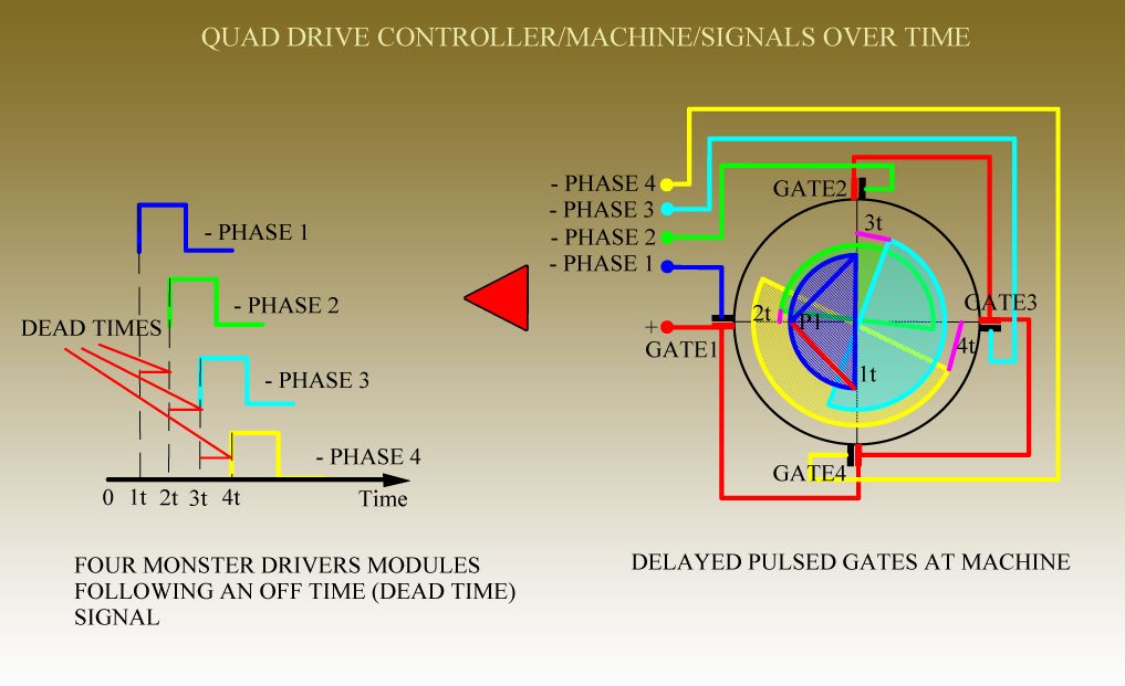 [/IMG]
[IMG]Posted by John Stone>>>The layout of monster driver was optimized for through hole components and was set to a 1/10 " grid in order to build it on a perf board with thousands of holes and pads. Either you use my optimized layout or you build it on perf board.
BTW: The monster driver was built for low frequency and very steep power edges. For higher frequency the opto will not perform well. It needs to be replaced by a faster one. Apart that the driver was specifically built for high current. The reason for all this was to get the Imperial setup running. It is no novice device. And it is opto isolated for severe applications.
I strongly recommend to use all sorts of other circuits presented earlyier in this forum. Usually 555 along FET performs quite well....
rgds John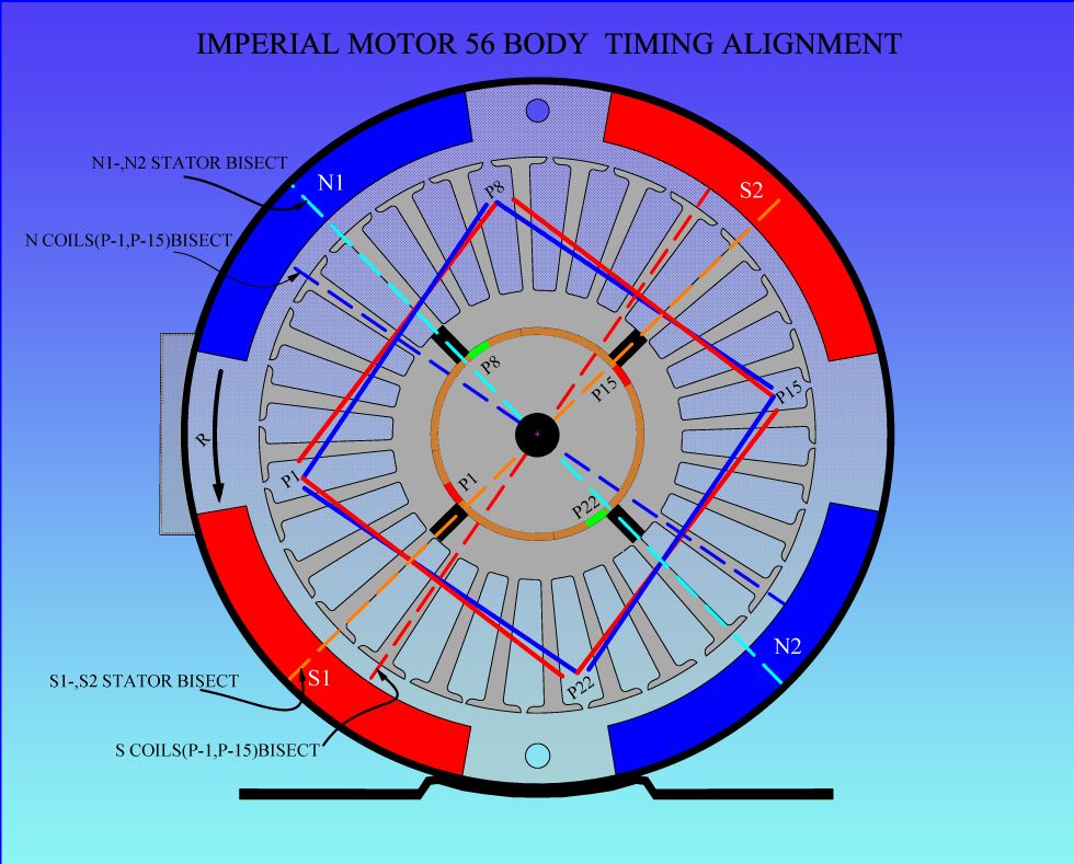 [/IMG]
If you are not familiar with this type of Motor...please search in my other Thread all the spec's given about it.
This Circuit works perfectly well As Is...
Regards
UfopoliticsPrinciples for the Development of a Complete Mind: Study the science of art. Study the art of science. Develop your senses- especially learn how to see. Realize that everything connects to everything else.― Leonardo da VinciComment
-
Monster Drivers...
Hello Thx1138,
This circuit was specifically designed by Engineer Sir John Stone to stand the reversed spikes, plus driving our Imperial P56 Asymmetric Machine...at a sequential pulse rate interrupted by some adjustable "dead times". And it requires Four(4) of this Monster Drivers to control all Four Gates of such machine.
[IMG][/IMG]
[IMG]Posted by John Stone>>>The layout of monster driver was optimized for through hole components and was set to a 1/10 " grid in order to build it on a perf board with thousands of holes and pads. Either you use my optimized layout or you build it on perf board.
BTW: The monster driver was built for low frequency and very steep power edges. For higher frequency the opto will not perform well. It needs to be replaced by a faster one. Apart that the driver was specifically built for high current. The reason for all this was to get the Imperial setup running. It is no novice device. And it is opto isolated for severe applications.
I strongly recommend to use all sorts of other circuits presented earlyier in this forum. Usually 555 along FET performs quite well....
rgds John[/IMG]
If you are not familiar with this type of Motor...please search in my other Thread all the spec's given about it.
This Circuit works perfectly well As Is...
Regards
UfopoliticsPrinciples for the Development of a Complete Mind: Study the science of art. Study the art of science. Develop your senses- especially learn how to see. Realize that everything connects to everything else.― Leonardo da VinciComment
-
Re: GChilders response to my dual stator arrangement
Hi Garry,Originally posted by GChilders post #2748 View Post
Yes I have a copy of your program, not sure how new it is compared to the one you mention here. But yes I see quite easily how to modify it for two stators TYVM! If not too much trouble, a comparison to your later versions would be appreciated. Did we establish how to monitor RPM and use it to stabilize the prime mover when used for AC generation? Gotta be an input pin on the arduino I'm sure, to handle that. I have the uno.
Been many moons now since I ordered all the stuff to make these, 'bout time to do it. Getting close...
accelerate under load: So far the only load I have applied is the second brush set to act as a motor, in series with the same battery that was running brush set one. Gotta do the video but seemed like the amp load immediately distributed across both brush sets evenly, the total maybe stayed near the same amount, but the rpms increased about 15%. Will take a closer look as soon as I can...
Hi JS, good to see your moniker back on these pages!
Last edited by sampojo; 05-13-2014, 07:42 PM.Up, Up and AwayComment
-
Monster Drive no longer available at OshPark
thx,
Did you see my conversions of JS Target 3001 layout to ExpressPCB last year starting sometime after page 66? My last there actually made it so you could separate the signal preconditioning board section from the Driver section, but thought that the whole redesign could be fruitless since JS was very cognizant of extraneous capacitances, etc. And that you could order the last Monster driver board v5.1 from OshPark based on the TARGET 3001 gerber files? looks like OshPark deleted my account but it could be redone, and he would also double layer traces no extra charge. Some debate on the value of R1, and a link was may have been omitted to no consequence if memory serves. Should we get them fired back up?
PS: your PCB is very compact, much like JS's. If it works we could get 2 independent sources of the PCB going.Up, Up and AwayComment
-
Hi thx...,
please find my answers below.....
I wish you get it right and running as the driver is a tool while the motor is the target of desire.
Originally posted by thx1138Experts spend hours a day in order to question their doing while others stopped thinking feeling they were professionals.Comment
-
Quad drive ready for the test
Hello Ufopolitics,
A few post earlier was posted a mockup about the redirect cores to transfer magnetic poles into the desired places of space. Link:
post254696
I designed a logic driver to drive four coil independently with variable frequency and variable duty cycle. Here is the schematic of this circuit. I am LTSpice fan, so it was simulated in LTSpice before building. Clicking to the link, you can download the free and very useful simulation tool. It works quite well for the hot electricity part of the design.
Here is the circuit:

The variable frequency (and the duty cycle) is controlled by the first 555 timer circuit (equivalent with your circuit posted on the forum). The output signal of 555 timer is shown as V(clock) in the LTSpice simulation plot (here above). The signal is divided by four using a 4 bit shift register 74HC194 and 2 pcs CD4093B (it is a 4 NAND gate with Shmitt trigger). The 74HC194 is good solution for the signal multiplier into 4, but it alone will lose the possibility of variable duty cycle.
V(q1), V(q2), V(q3) and V(q4) are the output from the 74HC194 4 bit shift register. Here we can change the frequency, but the output duty cycle is fixed to 100%.
See the output waveform of 74HC194:

Using CD4093B twice (as it is shown in the circuit) we can get back the possibility of variable duty cycle.
See the final waveform of logic drive:

Now, I will build the circuit and start the testing in the real environment.
In every clock cycle will appear the hot magnetic field in all core elements - e.g. in the top side will be all South and the bottom side will be all North and when the current will turn off, will appear the cold magnetic field in all places.

The drive circuit (shown above) will drive all four green coils in the core.
Output possibility: all driven coils, coils under the driven coils, and central coil or coils.
I hope that it can increase at least five times the creation of the desired effect comparing to the exciting one coil.
I will be soon here with the results of tests.
Have a good day:
Holbi "Knowledge is as good as it used."Comment
-
That is awesome Holbi!!
Originally posted by Holbi View Post
Excellent Holbi!!!
AWESOME!
I will get back with more time on this approach, I believe it should bring huge Radiant Fields In...
A couple of things...Orient the Main Core with the North-South as best aligned with our Earth Magnetic Polarity...
Second, I believe the Dual Layers Carbon Dielectric or Supercaps...will store Radiant without any problems...they have the ability to do minus charges as plus...and Oriented dielectric in carbon and radiant get along excellent...
Hoping this will help...
Regards
UfopoliticsPrinciples for the Development of a Complete Mind: Study the science of art. Study the art of science. Develop your senses- especially learn how to see. Realize that everything connects to everything else.― Leonardo da VinciComment
-
Freedom Development Platform - now is available
Hello Community,
I have just received a news about the new Freescale's Freedom Development Platform. It will be very useful tool - like Arduino - for the complex (quad or double quad) logic driver of coil exciting transistors.
Here is the newsletter message:
"Knowledge is as good as it used."Comment

 Tweet
Tweet


Comment