This forum is preserved as a permanent archive. The community continues at eMedia Press.

Announcement

Collapse
No announcement yet.

3D electromagnetic field

Collapse
X
 
  • Filter
  • Time
  • Show
Clear All
new posts

  • vrand
    replied
    Originally posted by Xenomorph View Post
    Hey vrand,
    there is magnetic flux in both coils at both ends as well as inbetween them except for the neutral zone in the middle. The magnetic field vectors of both coils are in opposite directions in regards to each other.
    Smith was of the opinion that there will also be opposite electron spin.
    The notion to "get amps" from one end is most likely taken from transmission line theory
    where under certain wave length ratios you would find current nodes and voltage nodes at predictable
    positions of the transmission line depending on how they are terminated/impedance matched.
    Hi Xeno
    That center tapped bifilar coil arrangement looked like what Mike was describing in his message above.


    To create the 3rd dimensional field you have to create an ANTIPHASE in your coils in the case of for example the Muller motor/generator. Your electromagnets are wound from the center of your ferrite rod, two wires connected but wound in opposite directions and terminating at each end.
    Later in the thread Mike showed another coil arrangement.


    The original coil arrangement for the EH/HZ design is shown in on the EH website pdf documents.

    EH Antenna Systems


    Right now I am trying to determine which coil arrangement works to generate free energy so I can try it out.

    Cheers Mike

    Leave a comment:


  • Xenomorph
    replied
    Hey vrand,
    there is magnetic flux in both coils at both ends as well as inbetween them except for the neutral zone in the middle. The magnetic field vectors of both coils are in opposite directions in regards to each other.
    Smith was of the opinion that there will also be opposite electron spin.
    The notion to "get amps" from one end is most likely taken from transmission line theory
    where under certain wave length ratios you would find current nodes and voltage nodes at predictable
    positions of the transmission line depending on how they are terminated/impedance matched.
    Last edited by Xenomorph; 08-26-2011, 11:27 PM.

    Leave a comment:


  • vrand
    replied
    Also when you mentioned bifilar coils this one from Don Smith referring to a coil that makes electric flux at one end and magnetic flux on the opposite coil end (coils wound CW & CCW from the center tap, only produces this).

    Originally posted by Michael John Nunnerley View Post
    To create the 3rd dimensional field you have to create an ANTIPHASE in your coils in the case of for example the Muller motor/generator. Your electromagnets are wound from the center of your ferrite rod, two wires connected but wound in opposite directions and terminating at each end.

    This will create the 3rd field which is a vortex field and NOTHING ELSE, from this you can design your motor/generator. You will have zero Lenze effect and will only draw current for the driving circuit alone. It is ALL in winding the coils in ANTIPHASE to create a unique vortex field, I will leave the rest of the design of the motor/generator up to you, I will probably get shot for what I have told you.

    Mike
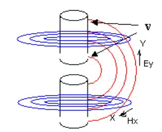
    Is the below photo what you where talking about above?

    Don says it the magnet flux end that is where one gets the amps from his free energy devices.


    Cheers Mike
    Last edited by vrand; 08-26-2011, 06:21 PM.

    Leave a comment:


  • vrand
    replied
    Originally posted by Michael John Nunnerley View Post
    Thank you for finding this, seems I need to keep my mouth shut in future. There is always someone trying to make money on others work and inventions.

    There is a problem with the description as what is shown is not exactly what happens.

    Mike
    Hi Mike

    Tesla used the spiral coil in his inventions and invented the bifilar spiral coil. Is this bifilar winding any good in creating the EH/HZ fields?


    Is this EH HZ design creating a magnetic longitudinal wave? Different from Tesla's electric longitudinal wave?

    Cheers Mike
    Last edited by vrand; 08-26-2011, 05:34 PM.

    Leave a comment:


  • MonsieurM
    replied
    Originally posted by Michael John Nunnerley View Post
    Thank you for finding this, seems I need to keep my mouth shut in future. There is always someone trying to make money on others work and inventions.

    There is a problem with the description as what is shown is not exactly what happens.

    Mike

    You are most welcome, you have shown us a phenomena that is quite important in our research in general, (for the simple reason that it exists in nature ) , so i guess good vibes are answering back

    Now, if i could ask you what is the effect resulting from the coupling because it could help us in the threads


    in other words, are the results described correct (coupling and all )

    Leave a comment:


  • Michael John Nunnerley
    replied
    Originally posted by MonsieurM View Post
    Check this patent out , i think you'll like it for inspiration sake

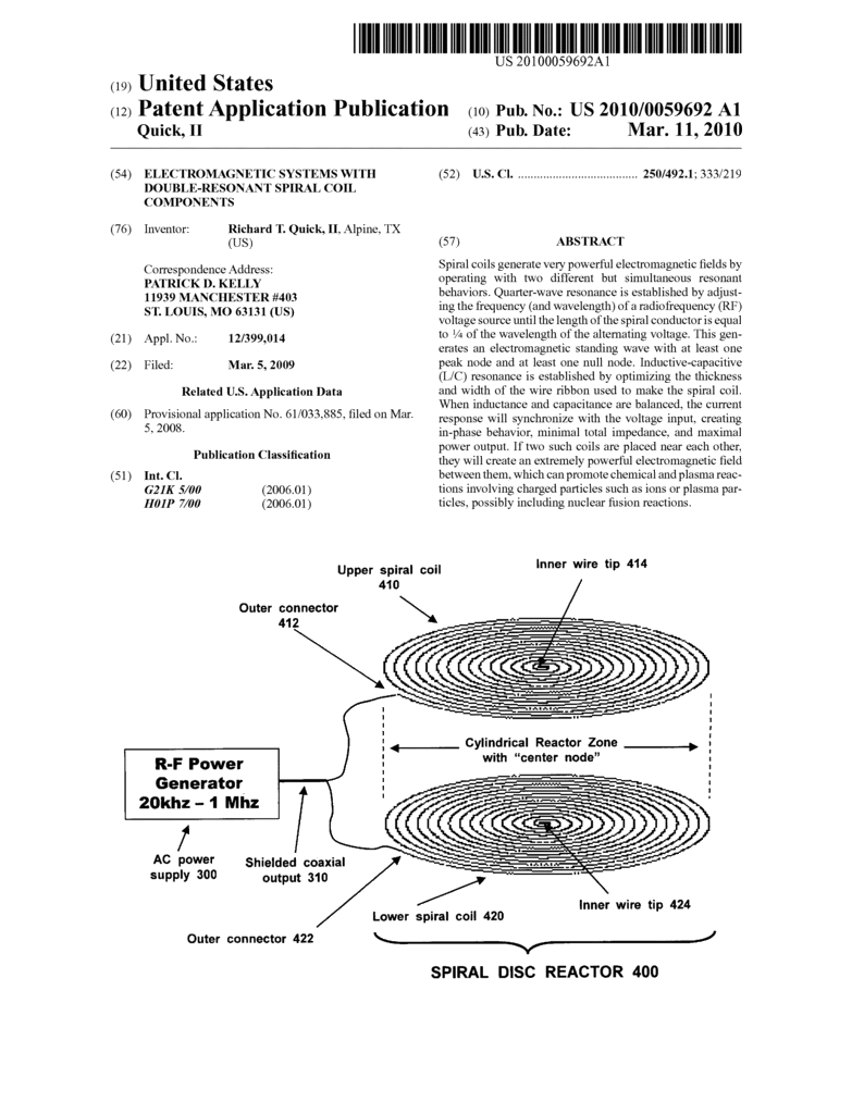
    ELECTROMAGNETIC SYSTEMS WITH DOUBLE ... - Google Patents


    Thank you for finding this, seems I need to keep my mouth shut in future. There is always someone trying to make money on others work and inventions.

    There is a problem with the description as what is shown is not exactly what happens.

    Mike

    Leave a comment:


  • MonsieurM
    replied
    Check this patent out , i think you'll like it for inspiration sake

    ELECTROMAGNETIC SYSTEMS WITH DOUBLE ... - Google Patents


    Leave a comment:


  • Dave45
    replied
    Originally posted by MonsieurM View Post


    Improvements in and Relating to Apparatus for Producing Electricity

    Roy Jerome Meyers


    Roy J. Meyers: Absorber (Atmospheric Electrical Generator)


    -----
    Felix Ehrenhaft: Magnetic Current --- 9 articles


    New evidence that there is another world of almost infinite minuteness, beyond the electron which only recently replaced the atom as the smallest thing in the universe, was brought forward by Prof. Felix Ehrenhaft of Vienna University at the meeting of the Association of German Natural Scientists and Physicians.

    I agree............

    Leave a comment:


  • MonsieurM
    replied
    John W. ECKLIN Stationary Armature Generator


    Abstract --- A permanent magnet motor in one embodiment utilizes a spring-biased reciprocating magnetizable member positioned between two permanent magnets. Magnetic shields in the form of rotatable shutters are located between each permanent magnet and the reciprocating member to alternately shield and expose the member to the magnetic field thereby producing reciprocating motion. A second embodiment utilizes a pair of reciprocating spring-biased permanent magnets with adjacent like magnetic poles separated by a magnetic shield which alternately exposes and shields the like poles from the repelling forces of their magnetic fields.

    Leave a comment:


  • MonsieurM
    replied


    Improvements in and Relating to Apparatus for Producing Electricity

    Roy Jerome Meyers


    Roy J. Meyers: Absorber (Atmospheric Electrical Generator)


    -----
    Felix Ehrenhaft: Magnetic Current --- 9 articles


    Last edited by MonsieurM; 08-18-2011, 12:08 AM.

    Leave a comment:


  • Michael John Nunnerley
    replied
    Originally posted by Xenomorph View Post
    @M: He wanted to have a pure capacitive effect between the windings.
    For that to happen they can't be serially conductively electrically connected.
    As soon as you connect the windings you are back on the pure inductive road.

    Actually the way you charge the individual coils is still inductively.
    Someone who has lots of copper wire lying around can try to get this concept somewhere by making 2 2000 turn coils and see what capacitance
    he'll get. Possibly best with the interchanging layer technique to increase area.
    Yes, you are right, but if you use litz wire you can wind this like an ordinary coil, but after say if it has 8 strands, separate into 4 + 4 and connect the start of one 4 to the end of that 4 and the same for the start and end of the other four, now you have your two connections.

    For this to work properly the frequency is very important and that will change depending on coil size and power of the rotor magnets "it has to be tuned", that will come with experimenting, you will not find a calculator to work that out for you, well not at the moment

    Mike

    Leave a comment:


  • Xenomorph
    replied
    @M: He wanted to have a pure capacitive effect between the windings.
    For that to happen they can't be serially conductively electrically connected.
    As soon as you connect the windings you are back on the pure inductive road.

    Actually the way you charge the individual coils is still inductively.
    Someone who has lots of copper wire lying around can try to get this concept somewhere by making 2 2000 turn coils and see what capacitance
    he'll get. Possibly best with the interchanging layer technique to increase area.

    Leave a comment:


  • mondrasek
    replied
    Originally posted by Michael John Nunnerley View Post
    Wind a bifiler coil, the start of one wire will be 1s and the other 2s, the finish ends will be 1f and 2f. Now connect 1s and 1f together and 2s and 2f together. what you have made is two coils with a capacitance built in joining them together. We do not want an antenna, we want a magnetic coil with a vortex field and this is one way to do it.
    Mike, are you sure you did not mean 1s to 2f and 2s to 1f like in the picture @scratchrobot posted in the other thread? I just want to be clear if your idea works differently or if the connections were mixed up. Like I said, it caused major Lenz drag on my system.

    PS, I changed the direction of the arrow in red from the original diagram.

    M.
    Attached Files
    Last edited by mondrasek; 08-15-2011, 06:45 PM.

    Leave a comment:


  • quantumuppercut
    replied
    Originally posted by Xenomorph View Post
    "Quitting wire capacitance" ?
    So you connect the coil in the regular inductive fashion and add a series cap?
    Yep, that's what I did

    Leave a comment:


  • Xenomorph
    replied
    Originally posted by quantumuppercut View Post
    If you put a series cap in addition to the open bifilar, then whatever lower capacitance would dominate the loop in my opinion. I quit using wire capacitance and go straight for series cap because I know you mention nanofarad wire capacitance. We need wattage.

    Hey mondrasek, that's very interesting information. Thanks.

    "Quitting wire capacitance" ?
    So you connect the coil in the regular inductive fashion and add a series cap?

    Leave a comment:

Working...
X