Announcement

Collapse
No announcement yet.

Tesla's Magnifying Transmitter "Replications"

Collapse
X
 
  • Filter
  • Time
  • Show
Clear All
new posts

  • Farmhand
    replied
    Well for me it's not about being able to buy stuff it's about being able to build
    stuff. Wheres the fun in buying neon sign transformers ? When I'm done I can
    say I build it all. I already run three transformers together I built myself.
    I build nearly all the buildings here, and all the fencing, I maintain all the
    machinery. And I do it my way.

    In case you didn't notice the wire in the Coil "A" and coil "B" will be exactly the
    same amount, length and weight. I don't need to tune it "Like Dr Stiffler either",
    The primary just needs to be tuned to the secondary. The secondary and extra
    coils will be just fine at whatever frequency they end up at. The primary just
    needs to be made resonant at the same frequency as the secondary or made to
    make the secondary "resonate" at it's resonant frequency.

    How to tune a Tesla coil.
    Oscilloscope Tuning a Tesla Coil for Resonance

    Tesla coil tuning video.
    Tuning A Tesla Coil with an Oscilloscope - YouTube

    The tuning is a well known procedure and and is no different from how any
    Tesla coil should be tuned. He tunes his primary by taps but it can be done
    other ways, the main thing is that it is done. I'll use taps too. There is no
    tuning of the secondary coils (except to each other), it is just not necessary
    otherwise when dealing with only one coil and if two are made the same only
    a small adjustment is needed. Unless there is a specific frequency to obtain
    there is no point. The resonant frequency of the secondary just needs to be
    determined, so that the primary can be tuned to it.

    The blown spark gap is to "quench the gap" same effect as magnetic
    quenching, it stops the arc and reduces "shoot through" as well as improve
    the effect and keep the spark gap cool.

    There's nothing complicated about what I'm doing except explaining it repeatedly.

    My HV transformer can work at different frequencies, at the moment i'm using
    it at 40 Khz, it works ok considering I just slapped it together, next one will be
    better. Try changing the frequency of a NST.

    That's the point the next one can't be better if there is no first one, to
    improve we must do. It's not imperative that you understand my ways or my
    motives. I will not follow someone else's path. I make my own path.

    This is not my only project I'm also building a rotating magnetic field AC
    motor/Transformer/Generator, and planning a DC electric drive for a quadbike
    which will have a regenerative system of my own design.

    Basically I do whatever I please because I can. And it's fun.

    Lighting LED's is a snap and I am bored with that. This video shows an
    unpowered transformer powering a 5 mm LED, It's not even ground connected
    if it is it works much better but i wanted to show it with no connection, it
    took me a few minutes to set it up. But I want to experiment not light LED's,
    of course it's just a receiver like anything else channeling energy from one
    place or form to another. Nothing creates energy.

    Free Energy Coils In Action.wmv - YouTube

    Cheers

    P.S I already ordered the 1 Klm of wire, I'll use for the coil "A's" and "B's".

    ..
    Last edited by Farmhand; 11-18-2011, 10:41 AM.

    Leave a comment:


  • Kokomoj0
    replied
    Originally posted by Farmhand View Post
    Hi all, I would like to present some plans I have of building some new coils and
    associated equipment. The new coils will be resonant below 200 Khz and capable
    of very high voltage.

    Specs;

    Coil A 300mm diameter 100mm high 0.5 mm wire, 160 meters 200 turns.

    Coil B 100mm diameter 300mm high 0.5 mm wire 160 meters 600 turns.

    Coil C 320mm diameter 40mm high 5 mm tube 2 to 4 turns tapped 5mm spacing between turns.

    This is what the coil will kinda look like.


    Uploaded with ImageShack.us

    Some more info on the estimated values.


    Uploaded with ImageShack.us

    This is what it should be capable of with one turn and 10 000 volts input.
    Over 1 000 000 Volts. Click the image to be able to read it.


    Uploaded with ImageShack.us

    Large picture
    Imageshack - coilspecsbig1.jpg

    This is how I'll power it up.


    Uploaded with ImageShack.us

    This is how I intend to build the adjustable and air blown spark gap.


    Uploaded with ImageShack.us

    I'll blow it like this.


    Uploaded with ImageShack.us

    And I intend to build a special little shed for experimenting in it'll have more
    room than the drawing suggests, it'll be bigger.


    Uploaded with ImageShack.us

    And here's a video of an experiment with terminal leakage.
    Terminal Leakage.wmv - YouTube

    So I will probably deconstruct my low voltage coils for the wire but I'll ht them
    with a spark gap before I do that.

    Cheers

    ok what I do not understand is why you are at least from my knowledge base making this so complicated? at least that is how it looks again based on my knowledge base?

    My understanding is that the b coil is a free resonant coil so it seems to me you would tune it much like stifflers methods using a spectrum analyser to start and then building the second as close as possible to it starting with the same wire lengths and mass etc.

    then what is wrong with buying an elcheapo 1 amp 15,000 volt neon sign transformer and some 30 kv neon sign wire?

    Could get 2 of them and fw rectify it and start with what is fw again 2.14x30kv? The higher the voltage you start out with the lower the coil resistances required to get your desired Vo and the sharper the Q will be at resonance.

    stuff:
    JavaScript Power Calculator
    Inductors
    Coil Construction Techniques - HAMwaves.com
    RF Inductance Calculator - HAMwaves.com

    If that interests you then you could either buy hv transmitter type diodes or just string 50 x 3 kv diodes in a row for each leg. LOL

    Then for the air why couldnt it just be a rotary disk that is hollow on one side with holes drilled on the outside rim face to cut the air off from the pipe at whatever speed you dial in on your vari speed motor? then correspond how many holes you have and the motor speed to the freq you wish or do I completely not understand what you are trying to accomplish?

    Can get fancy and sample it part way up and put a phase and voltage sensor on it and let it self tune to the resonance.

    those 15kv neon xformers will hold a nice 4" arc either ac or dc, or step it down to 7500 or whatever v you are looking for and dont forget the screen cage to work behind.
    Last edited by Kokomoj0; 11-18-2011, 08:39 AM.

    Leave a comment:


  • dambit
    replied
    This forum needs a like button. I like the idea of your dedicated shed.

    Leave a comment:


  • Farmhand
    replied
    Here's a couple of Idea's I have to use two HV transformers opposing, it could
    be done with two MOT's or two ignition coils also in anti-series (as I call it) with
    AC. By anti series I mean the two secondaries are connected Negative to
    negative and with CCW-CW coils I connect the negative of the CCW primary to
    the negative of the CW primary so then the two positives are connected to AC
    and the HV is at each outer end of the coils and summed to double or can be
    connected in parallel for more current lower voltage.

    With two CCW wound coils just connect the negative of one primary coil to
    the positive of the other coil, that should do the same thing.

    Secondaries summed together.


    Uploaded with ImageShack.us


    This is how I'm using mine at the moment and this way lower voltage coils can
    be used to get higher voltage.

    Secondaries used for Higher voltage.


    Uploaded with ImageShack.us


    Leave a comment:


  • Farmhand
    replied
    Transmitter Station

    Hi all, I would like to present some plans I have of building some new coils and
    associated equipment. The new coils will be resonant below 200 Khz and capable
    of very high voltage.

    Specs;

    Coil A 300mm diameter 100mm high 0.5 mm wire, 160 meters 200 turns.

    Coil B 100mm diameter 300mm high 0.5 mm wire 160 meters 600 turns.

    Coil C 320mm diameter 40mm high 5 mm tube 2 to 4 turns tapped 5mm spacing between turns.

    This is what the coil will kinda look like.


    Uploaded with ImageShack.us

    Some more info on the estimated values.


    Uploaded with ImageShack.us

    This is what it should be capable of with one turn and 10 000 volts input.
    Over 1 000 000 Volts. Click the image to be able to read it.


    Uploaded with ImageShack.us

    Large picture
    Imageshack - coilspecsbig1.jpg

    This is how I'll power it up.


    Uploaded with ImageShack.us

    This is how I intend to build the adjustable and air blown spark gap.


    Uploaded with ImageShack.us

    I'll blow it like this.


    Uploaded with ImageShack.us

    And I intend to build a special little shed for experimenting in it'll have more
    room than the drawing suggests, it'll be bigger.


    Uploaded with ImageShack.us

    And here's a video of an experiment with terminal leakage.
    Terminal Leakage.wmv - YouTube

    So I will probably deconstruct my low voltage coils for the wire but I'll ht them
    with a spark gap before I do that.

    Cheers

    Leave a comment:


  • Farmhand
    replied
    Very good dR, Yep I got neons but they weren't coming on that I noticed but I
    didn't really look I noticed the smell and shut it down. Maybe the broken tank
    cap caused it and/or the tank caps too small for the power I was using.

    Yep again, I just use a FWBR for the AV wireless thing but I use an electrolytic
    capacitor on the DC to run the light or device from.

    I must have missed it are you using a different receiver coil for the sub ? Good
    work any way and very interesting, I'll check it out again. Keep us posted I know
    Slider is interested in RC stuff and that's what got him into this adventure. He
    might join in, I hope to find something similar to try. It's all so damn interesting
    to mess with it's no wonder it is kinda suppressed.

    I could try a RC plane or chopper I have plenty of room. Then the
    trick might be to make the Transmitter give off more Hertz waves more like
    70/30 Earth current/Hertz waves than 95/5 Earth current/Hertz waves, that
    way the dedicated receiver would still work too. 80/20 might do, but sine
    wave still.

    Check out my next post, lots of drawings, new coil build coming soon.

    Leave a comment:


  • dR-Green
    replied
    Originally posted by Farmhand View Post
    Hi dR, that's sounds like a good way to make spools. Ishould have mentioned before also that I read it's a good idea to seal the PVC pipe with a insulating coating. Apparently the PVC is slightly conductive. And I do see arcs going right through it. I haven't sealed any of mine though, but something to keep in mind, I didn't see it as very important with the low voltage setup. But I think it would be advantageous.
    Yes good point. I also should have mentioned this sooner. I'm using white PVC for these small coils because according to the guy at the Geek Group the black colouring of PVC is from carbon, and that would be even worse. I think a lot of non-conductive things become somewhat conductive with these applications though. The coil output is even arcing into wood.

    Sounds like you had a lucky escape not to destroy anything Are you using a neon across the fets at all? There's a lot of stuff to pay attention to with the HV, that's another reason why I think a simple NST setup would be better. Only the spark gap to adjust then. I broke a 2N3055 the other night when using two of them instead of the BUX81. I assume it was the spikes that did it because they looked pretty huge. With 2x 2N3055 (more gain than the BUX81) the neon wasn't just orange or pink, there were really bright white/purple flashes as if it was arcing inside, and I only saw that twice before the transistor was completely destroyed. So getting more power into the spark gap/TC is a real problem with this sort of setup I think.
    I've been zapped a couple of times working on this submarine, it hurts a bit, the last one got me pretty good on the back of my finger Water seems to be quite safe when it's energised, but metal objects placed in the water produce sparks that burn.

    I made a FWBR out of 1N4148 diodes and it's much better than an AV plug. It still works off one wire, and even though the sub is 4.5v, the unconnected AC wire of the FWBR produces sparks that burn.

    I also tried the bigger coil and the sub performance got even better again so I think I have a theory emerging that goes something like this... Bigger coil = lower frequency = bigger capacitor = bigger discharge = more power for use.

    [edit]... With exactly the same input.

    That seems to be the way things are pointing at the moment.
    Last edited by dR-Green; 11-17-2011, 11:56 PM.

    Leave a comment:


  • Kokomoj0
    replied
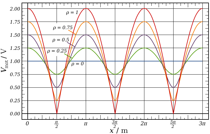
    here is a link for vswr


    Standing wave ratio - Wikipedia, the free encyclopedia

    VSWR measurement


    Leave a comment:


  • Farmhand
    replied
    Hi dR, that's sounds like a good way to make spools. Ishould have mentioned before also that I read it's a good idea to seal the PVC pipe with a insulating coating. Apparently the PVC is slightly conductive. And I do see arcs going right through it. I haven't sealed any of mine though, but something to keep in mind, I didn't see it as very important with the low voltage setup. But I think it would be advantageous.

    Cool idea with the submarine. I like it.

    The spikes can be a real problem I almost cooked my mosfets running the spark gap using about 2 amps through the supply transformer with the recovery not connected to the charge battery. The mosfets were burning hot. And on top of that later on I almost burned up my charging inductors and nearly blew one of the primary charging capacitors on the supply transformer it swelled up like a balloon. I was seriously straining the tank. I think I fixed that by using larger capacitors and refitted the de-q-ing diodes.

    I think with a transformer to avoid the spikes we can just use an almost 50/50 duty to pulse the two primary coils back and forth to make the AC this eliminates the spikes mostly, I think by flux cancellation. But with pulsing a coil like an ignition coil from a cap it is not so easy.

    I'll try to explain what I think about spikes. Just take a standard Bedini setup as an example. The charge battery is in series with the source so the spike gets directed to 12 volts or so higher than the source voltage if you were using a step up transformer that would reduce the secondary output a bit, anyway the charge batteries can be put in series to the point where the neon will come on even when the charge batteries are connected, I think it would take 5 or 6 charge batteries. My point being I don't think there is any easy way around it. I see only two ways of dealing with the spikes is either to ground them which is dodgy because I think it causes more power use in some setups, or direct them back to the source through a higher potential like a charge battery or something else.

    I fully understand you not wanting to charge batteries if there is no need to do it.

    I wish I had a suggestion but I don't. Not at this point at least.

    Thanks for the PDF too. Awesome.

    Cheers

    Leave a comment:


  • dR-Green
    replied
    Originally posted by Farmhand View Post
    I can't believe I ran out of secondary formers/bobbins I'll have to unwind and
    rewind the CW one to CCW to test with all CCW wound coils as I tested
    before and compare the results, I think that is the scientific way to see the
    truth.
    My Bedini coils (spools) are made from a circle of 12mm thick MDF glued onto 20mm conduit. Strong glue and some creativity (dig out a groove from the MDF where the conduit goes so there's a "lump" of glue stopping it from slipping off) holds the whole thing together. The good thing is you can make any size, as big as you can get a holesaw/cutter and as many as you want, and you don't have to wait until you've used all your wire before you have a free spool. My first coil started coming apart literally when I put the last turn on, so good glue and a good thick piece of MDF for more contact is essential.

    I might be interested in buying a couple of those boards off you

    I'm having some issues with the HV spikes. I don't really want to charge a battery there, ideally I'd like to just send the energy back round if it's possible. But this submarine project has revealed something new. I started adding salt to the water to try and get more conductivity. While the reception at the sub got better, the neon started coming on stronger and stronger until I reached a point that the maximum power in the sub coincides with a permanently lit neon. So maybe this will call for bigger terminals at the other end? We'll see how it goes.

    he idea with the series of step up's in potential in that sketch is to get
    excessively high voltages on the two slightly curved plates just far enough
    apart so as not to spark and look for effects. The top plate could be
    suspended by a flexible cable, so it can be observed for movement. The
    bottom plate could be turned over to create a cupping effect also.
    That sounds good. I think an additional way to get really strange effects is to adjust the discharge duration, or in other words to have complete PW and frequency control over the spark gap. Gerry Vassilatos covers very strange and dangerous effects in his book Secrets of Cold War Technology.

    Gerry Vassilatos - Secrets of Cold War Technology.pdf

    Leave a comment:


  • Farmhand
    replied
    The transmitter resonates with the planet at some harmonic of the planet and any
    receivers resonate with the planet also and by default the transmitter. The
    magnifying transmitter only needs to be a single transmitter tower to be tuned
    and ready so to speak. It wouldn't make a whole lot of sense to run a transmitter
    without there being a receiver but it can be built and tuned, it would just
    have nothing to transmit to.

    If using a wire as the medium to transmit through then the Transmitter would
    need to resonate with that and the receiver, but that is not how it is
    intended to work because the wire will radiate energy, whereas the Earth would not
    radiate energy like a wire.

    That's why there is only one in the patent, they are all similar and are
    tuned in to the planet.
    The transmitter could work at say 20 004 Hz @ 1667 x 12 Hz,
    and one receiver could work at 9996 Hz @ 833 x 12 Hz,
    and another at 15 000 Hz @1250 x 12 Hz, but to get the most power a receiver
    would need to work at the same frequency as the transmitter.

    Where as with the other system there needs to be two to be tuned to each
    other I think and so there is two in the patent drawing.

    And unlike some people think and say all the energy used at any receivers
    would need to be put into "the" or "a" transmitter, if a receiver is outputting energy
    that energy needs to be put into "the" or "a" transmitter primary.
    There can be more than one transmitter of course.

    It's a system of energy transmission not a source of free energy and not
    power transmission either it's energy I think it's an important difference.

    Cheers

    Leave a comment:


  • dR-Green
    replied
    Originally posted by Farmhand View Post
    Hey dR, Very impressive results from you're little coils. Are they special bulbs the
    filament/plasma hybrid bulbs or did you make them hybrid bulbs by applying
    excessively high voltage to them. Nice work you can raise and lower the
    primary and/or the secondary to alter the coupling ? Thats another difference
    between a magnifier and a regular Telsa coil is the magnifier has close coupling
    but a Flame thrower has loose coupling. Spirals have a fairly close coupling too.

    I would like to try a spiral primary and secondary with a helical "extra coil"
    resonator. It would be like making a spiral transformer into a magnifier. Kinda like
    what I did with the garden light coil with a conical secondary and helical
    extra coil" and inverted conical primary.
    I dare say that these small coils might be slightly better at lighting the filament than the spirals at the same input. The hybrid thing is just a 40w bulb connected like this


    But I'm holding the 8w fluoro on a stick instead of the 4w. The fluro seems to "ground" it and the filament starts to light, but it's not grounded enough to make the plasma go away. I was getting better effects than that but things are always different when I press record I spend ages in the video tweaking it trying to get the effect when earlier it was easy For some reason most/all bulbs I've tried produce plasma with one wire except the 15w ones

    The primary can easily be moved, but holding it in place higher up will need some extra pieces, but it shouldn't take a lot of work.

    Before making these small coils I wound one of the wires on a piece of conduit so I'd know how much I'd need to cut and where to drill holes etc, and I tried it as an "extra coil". I only did one quick test and the result wasn't good, could be due to a number of reasons like wound in the opposite way. Haven't tried again since winding them properly.

    The latest piece of test apparatus I'm working on is this thing


    RC submarine It's a bit small so I might have trouble in terms of capacitors and what not, but I'm getting some results so far. I have the TC output going into a tub of water, connected to a piece of metal, and an apple pie tin on the other side connecting to an AV plug going to where the battery used to be in the sub. So doing the tests on dry land before setting sail I'm getting about 2Hz bursts of thrust so far, using a 2200uF cap that will fit inside. But I'm not sure that the cap makes it any better, just the bursts and pauses are longer than without it.

    A big enough model to fit a receiver coil on would be the way

    Leave a comment:


  • Kokomoj0
    replied
    Yes I htink that is a part that has been overlooked in these designs.

    Once we talk about wave length as being required to convert the energy it screams to me that an impedance match must be there somewhere and that screams antenna techniques now come into play.

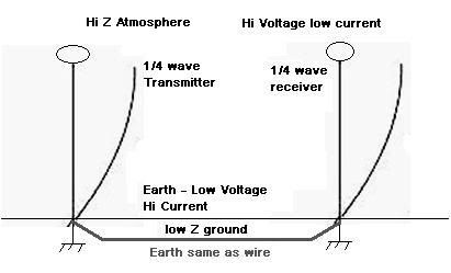
    You need at least 1/4 to get or should I say be at the maximum voltage node which we presume to be at the top. You need the hi voltage to get conduction because the atmosphere is closer to an insulator than a conductor and on the other hand you need the hi current to be directed to the ground.

    Antenna matching is the key to creating an impedance matching scheme for a 1/4 wavelength which is 1/2 of the dipole which is necessary for transmission.


    wiki has a fairly decent write up on it

    Dipole antenna - Wikipedia, the free encyclopedia


    This is interesting video showing the 1/4wl radiation.

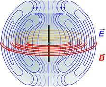
    Quarter wavelength monopole electric and magnetic field animation. - YouTube


    Now tesla says it does not radiate and that may be true in the electromagnetic sense through space, but it would pulsate current into the ground as a result of the oscilations and it somehow would need to set up resonance with the receiver and since resonance is key it is radiating something or it would not be able to do this. Leakage maybe? through the earth maybe?


    .
    Last edited by Kokomoj0; 11-16-2011, 06:41 AM.

    Leave a comment:


  • Farmhand
    replied
    Sorry for all the posts.

    You brought up a good point Kokomo about if the coils were at 1/4 resonance.

    This is interesting because without being connected to the ground with the
    bottom of the secondary I think the point of maximum potential can shift
    down the coil "B". however I've found that the coils are much more stable if I
    connect to and transmit through a plant pot full of moist dirt, dR uses it too
    which is where i got the idea from, but it was originally posted by Antigravitics
    a while ago.

    Anyway if the ground wire is substantial enough and well enough insulated it can
    work OK, but there is still some coupling to the ground with the wire laying on
    the ground I think. I haven't tested the coax cable yet but when I do I'll know
    if there is an improvement.

    Back to the coil rewinding good fun.

    Cheers

    Leave a comment:


  • Farmhand
    replied
    P.S. Kokomo I welcome any technical insights you or others may have. But I
    have put considerable thought and research into this covering most of the
    practical aspects, and I think dR will agree when you see one work on video
    there is a bit of something lost in the video, to see them working first hand it is plain to
    see the energy used at the receiver got there through the ground wire
    (connecting wire between the bottom of the secondaries) just like Tesla say's
    in Tesla's work on alternating currents court case.

    And it's also easy to see a lot of other stuff he says is true and what Eric says
    is true too. There are a lot of different aspects and slight variations of wireless
    energy transmission.

    The beauty of the three coil magnifier setup is the secondary coil "A" is
    closely coupled to the primary "C" but the extra coil "B" is narrower diameter
    than "A" and going up in altitude, so the higher potentials are away from the
    primary and very importantly, away from the ground.

    It would be difficult to use a spiral coil only a few meters from the ground with
    1 000 000 volts at it's center only a few meters from the ground, that
    wouldn't work so well. It needs to go up in altitude as the potential at the end
    of coil "B" and the terminal goes up.

    Leave a comment:

Working...
X