
Colorado Springs Notes, July 8, 1899. Page 67. Tesla explains about if the break
rate is much less than the free vibration then the primary inductance is better to
be great but if the break rate is about equal to the free vibrations the primary
inductance is better to be small.
It's all there in black and white. And it is just as I said. If you want to use a
fraction of the resonant frequency then it's best if the primary is matched to the
secondary as in the resonant frequency so that the primary vibration continues. But if
the break rate is equal to the resonant frequency it doesn't matter so the
primary can have as little inductance as possible because the vibration in the
primary doesn't need to continue.
The primary is best with only one turn only if the break rate is to be about the
same as the free vibrations of the oscillating circuit, which I also said was the
best case scenario which is to use a break rate equal to the resonant
frequency, as I did with the solid state setup. Then i made the primary match
the resonant frequency of the free vibrations so I could get good results from
using less than the resonant frequency to pulse the primary.
I recommend people should read the Colorado Springs notes as well. But keep
in mind they are notes and also note there are many factors determining the
best arrangement for a given want or need.
Absolute theoretical optimums may not always be practical, as I believe Tesla
shows in the notes.
Cheers
P.S. Tesla also comments there somewhere that considerations should be
made depending on what it is exactly you want to do with the setup. After all
if we want to use it to make lightning we can, Tesla did.
And it is simply not true that no one "gets" that the terminal is not the output.
I get it and I have explained it quite a few times in this thread. The energy is
transmitted through the ground or conducting medium.
However one way to see roughly how much potential is on the terminal is to
check causing it to arc to ground by forcing a "leak" or using some other
indicator to gauge it in comparison to previously.
All my comments about Eric were in response to others, and should be
considered in the context they were given.
Cheers
-
And besides, you need to explore your surroundings in order to know where you were to begin with
Anyway, I do believe that Eric's comment has been quite helpful, combined with the limited experimentation so far. This might not be an accurate way of describing it in words, but I think the solid state method would need "many" primary turns to tune it efficiently because the relatively low power disturbance needs to excite the secondary somehow - so you need a bigger hammer as in the analogy below. But with big discharges, or harder strikes, you can use only one turn, sort of like you hit a bell in one spot and then the whole thing resonates. (Also any attempt to hit it in different places at the same time will have a damping effect and stop the ringing, and so will using a bigger hammer due to the bigger surface area making contact and damping the vibration). So you do (some of) the tuning with the capacitor and spark gap, which is the rate and force with which you hit the bell if you will. So the primary simply acts like a hammer, delivering "strikes" that cause the "bell" secondary to "ring" or resonate. The secondary is tuned to quarter of the rate that you're banging the hammer, so that the voltage peak occurs at the end of the wire or the terminal, not further down and result in a ball of fire as we have previously established.
That all seems relatively straight forward if I've got it right. So I suppose the next unknown is the relation of the secondary to the extra coil.Leave a comment:
-
Originally posted by Farmhand View Post To begin with you titled the thread using the term "Replications", not Replications. Also Peter contributed on the first page so this divergence if you will is made clear from the start. Then we have both essentially been going our own directions with it while at the same time sharing results. The thread is full of terms such as "I think", "I believe", "in my opinion", "I will test" etc etc. The whole thing is open and there are questions throughout. If someone comes along, reads it all and then builds it wrong when they expect it to be right then they haven't noticed the fact that it's all a process of discovery. There are no instructions in post 1 as to what everyone must build and nothing is hidden. But I think it would be fair to say that Eric hasn't read through the entire thread (in fact neither have I), so it's not really a valid or fair judgement to base it on page 1 when a lot has developed since then. So I wouldn't be too concerned about it. I don't think you are the reason why I'm not getting it
  I'm not getting it for the same reason that someone who got on a bike for the first time 5 minutes ago isn't getting it. That's the purpose of getting back on and trying again.
Also don't get me started on the "let's all sit on our asses until someone else comes up with the answer and then we'll use it, and if it's wrong we can all blame him" method of modern humanity. If they sat on their ass and waited for the answer then they have only themselves to blame when it all ends up in a big mess. As long as one doesn't proclaim to be the source of all knowledge then I don't think there is any connection or basis for blaming that source for one being misled.Last edited by dR-Green; 12-10-2011, 08:24 PM.Leave a comment:
-
Here's an example of kinda what I'm talking about. I'm a qualified metal
fabricator/welder (boilermaker). I can do structural steel work, gas pipe
pressure welding ect.
If I seen my next door neighbor fabricating and welding the frame for his home
made dune buggy without properly preparing the joins to be welded or without
the proper gusseting, I'm not going to go to him and try to tell him he needs
pressure pipe quality preparation and welds or that he should use a special
procedure to perform the welding so the frame does not become distorted or
weakened. Because it's not necessary it's a home made dune buggy not a
$250,000 custom race car. A backyard builder does not need to know the ins
and outs of gas pressure pipe welding procedures or other such complex things.
A backyard builder can cut corners for convenience the buggy will still work,
even if corners are cut the invention will be more or less realized.
If on the other hand I seen him I seen him using a dangerous procedure on a
tow bar or tow hitch for a road bound vehicle which could be dangerous to
others I would say something and in no uncertain terms warn him of the
possible consequences of it failing while in use.
(eg. people getting killed by a wayward trailer) and jail terms.
We should keep things in perspective. My Tesla transformers are not going to
kill anybody.
Same thing with this. Theoretical optimums are not required, Tesla states as
much in the patents.
The information required to build, tune and operate a Tesla Transmitter is
contained in Tesla's patents.
I don't intend to have a whole town full of households relying on power
transmitted through my experimental setup. So I don't have much to worry
about. I don't profess to be an expert or to have built a perfected system.
I don't see how I could be the reason other people don't "get it". I can hardly
be blamed for people not "getting" what Eric is teaching them.
I didn't do any high school electricity class, and I don't play with Tesla, he's
dead.
Furthermore I do not need to ask for Eric's permission before I post my opinion
on a particular matter. And I don't think people should be worried about what
Eric thinks. We can tinker with whatever we want.
CheersLeave a comment:
-
Besides, at the present time I am working on designing and building the required
equipment to transform the stored energy in my batteries to HV DC in a cap
bank. As a power supply to power my experiments. When I'm done with the
power supply I will know how much power I can use. Then I will build some more
coils using the experimental data and experience I've gained, and have some
more fun.
I'm winding a annular core now with four transformers for experimenting with, I'm
making it so that when I'm done experimenting with it, it can be used for a
regular 12 to 240 volt AC inverter.
CheersLeave a comment:
-
Eric is allowed to be pissed off but he'll have to get over it, because EricOriginally posted by jpolakow View Post
doesn't rule over me.
As for the one turn, while that may be true that one turn is best. And Tesla
may have used one turn at Colorado Springs. How many Turns was on the
Long Island Transmitter ?
My contention was that one turn is the theoretical optimum and the Earth
wont split in two if more are used. I don't think Tesla would mind that we use
more than one turn.
The transmitter I built here is solid state, should it also have only one turn ?
Even though it is powered with 12 volts and transistor switched.
In my opinion the primary/secondary resonant frequency's should match for best results,
that could be difficult to achieve with one primary turn on some setups. I
don't think it is absolutely necessary they match, and the matching can be
done different ways.
This is a perfect example of why I don't take to Eric. He's a name caller. It's
unnecessary. I bet I know a lot of stuff about non electrical stuff that Eric
doesn't know, does that make him an idiot or moron ?
When I said Eric had never built one any more than I have, I was talkingAnd by the way any idiot can make a Tesla Transmitter out of
the information provided in that book.
about a system that transmits power using the ground over a distance,
enough to light lights, over more than a few meters with high efficiency.
No where in this thread do I propose to be an Expert and "know" everything.
But the fact remains, I can do whatever I want as long as I don't break any
laws. I can experiment any way I so choose. And I will.
If Eric was to try his hand at something he had no previous experience at, but
something I was well experienced at, and he made some mistakes or was
thinking the wrong way, I would not call him an idiot. I would praise him for
trying then offer some help, or leave him alone.
Unfortunately for me, I take an instant dislike to condescending name calling.
jpolakow, where is your transmitter ? Where are all the devices Eric's thread
followers are building ?
How many Primary turns are on the spiral transformer in the pictures above ?
How many primary turns were on the long island transmitter ?
I honestly have had not much more than a quick skim through Eric's papers.
Mainly because I like to experiment more than read and I like to think about
things in my own way. I have referred people to Erics papers if they want to
get Technical. I don't dispute his work at all. But everybody doesn't need to
do everything Eric's way. It's a free world.
After the research and experiments I have done it's my opinion that to
transmit energy using the ground as a conductor with good efficiency a
frequency of 20 Khz or less should be used, as Tesla states.
So what of the comment by Eric that the rotary parametric transformer
outputs more power than is input ? After all that setup is only about 53 % efficient.
The guy asked for pointers to an experiment or free energy device of aroundOriginally Posted by vrand
Hi Eric
Can you please suggest a simple experiment/device where we can build a free energy device to power our homes and cars? Around 10 kw power output?
Cheers Mike
Here is Eric's reply on his Yahoo egroup n6kph forum:
n6kph : N6KPH
Thank you Eric
Cheers Mike
>>>>>>>>>>>>>>>>>>>>>>>>>>>>>>>>
From: Eric Dollard
Sent: Friday, September 30, 2011 1:55 PM
To: [email protected]
Subject: [n6kph] Response to the forum
Santa Barbara Rotary Parametric Transformer, tested gave transformation
ratio, power it to power out, of 108% +or- 5% error of measurement. It
works, see video.
10 Kw to power a household, if he already had power to feed to a rotary
parametric transformer I don't think it would be advantageous to lose 47 % of
that power by feeding it through a Rotary Parametric Transformer.
Cheers
.Leave a comment:
-
Well, some of my personal demonstrations and the construction of my spiral coils are obtained directly from Eric's Borderland Sciences video, so if I'm not doing it right, then it's not my faultOriginally posted by jpolakow View Post All appears to be on track based on the fact that I can light an incandescent bulb in my hand without a direct wired connection to the coil, the same bulb attracts aluminium tape, there is no need for closed loops, and the receiver receives at the other end as intended. In other words Eric's demonstration has been replicated. It has all been recorded on video and published on youtube, so what can one say
  If none of this is correct then I would argue that it's necessary, personally, to progress this way in order to get it. Unless someone is happy to just hand me a complete design, including all the measurements, of what I should be building. That would be greatly appreciated But thanks to Eric anyway. I don't know if he's referring to people personally, individual posts, or the whole thread in general and everything we're doing here is wrong, but all I can say is I've replicated what he demonstrates in one of his videos, so if all that is wrong, thanks anyway because it's all certainly very interesting and it all works like he showed
Leave a comment:
-
Just a quick disclaimer here. This is response is from Eric Dollard. Not from me. Eric's words directly. Eric is "pissed off that people aren't getting it." "They are getting way off the track." "And there's no legitimate reason for it".Originally posted by Farmhand View Post
How many turns did Tesla use at Colorado Springs? One- there is a reason for that. It's only with one turn that you can get the maximum amount of capacitive dishcharge with only one turn. Read the Colorado Springs notebook. For never building one, why is there a picture of me with a wireless Tesla Transmitter lighting up a light bulb in two peoples hands on the cover of "Condensed Intro to Tesla Transformers"? With no wires! And by the way any idiot can make a Tesla Transmitter out of the information provided in that book. It seems to me there's a lot of people who need to go back to high school electricity class before playing with Tesla. Don't bog the world with your miscomprehensions.Leave a comment:
-
I think but I'm not sure, my 6mm diameter spark gap copper rods are expanding with the heat I normally leave it shorted out when it's not being used, and the last 2 times I've come back to it it's no longer shorted. So it's either unscrewing itself or something is changing size.
Leave a comment:
-
You can watch the film here
The Secret Of Nikola Tesla - YouTube
Or download it here
Secret of Nikola Tesla - The Movie (Tajna Nikole Tesle) (1980).a (download torrent) - TPB
I don't know if Tesla built one that size or if it's just for the film, it appears to be working because you can see what looks like series spark gaps in one of the pictures. I like the size of it anyway, could be good to experiment with something like that. I'm interested to follow the same kind of progression and try the same kinds of things to see where it goes. I could read things all day explaining what and why, but nothing beats doing something and then seeing the effect.
My dowels have all been pine so far, got a hardwood one but haven't tried it yet. Haven't had any problems with it so far, I don't know how "reasonable" it is to be concerned about the resin in the pine. But only my primaries have been on pine so far, haven't tried any really HV.
Yes I'd like to make one like that too, maybe I'll copy your design when you decide everythingI would really like to build a scale model of the Magnifier patent picture,
complete with wooden supports, the hood and tube conductor. It would still
be at least 600 mm high though.
Reminds me of that Egyptian image with the dudes in sunniesI'm still looking for the picture of four spiral transformers i seen before, they
are mounted vertical on a central dowel or core maybe and appear to be for
four phases of supply or conversion. My guess is they were four HF transformers
for a 4 phase HF HV supply.
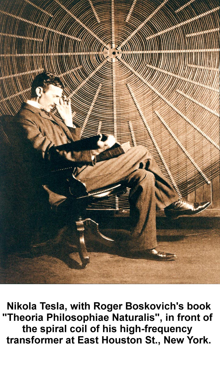
It's basically that image of Tesla with the book I copied for the design of my spirals. I can see in that picture though relative to the spot in the centre, the supports are positioned so it does spiral progressively with no "cross over" sections like you'd have with layered turns.
Yes I can see 8 turns that looks like the primary. I think in the patent he says single turn primary though, can't be sure. I wonder what the timeline is with all these pictures and patents. Could be an interesting coincidence anyway, I wasn't aware that Tesla might have added an extra coil to the spiral like that. It does look like that's what's going on
Off to make two mini secondaries with the 13 metres 26.6g 24 SWG wire now
Leave a comment:
-
Those are some interesting pictures, it's interesting to think of the possible
progression of the modification to the Transformer.
It looks to me like he built this one first, and wound it right on the wall.

Uploaded with ImageShack.us
Then I assume he developed very high voltages which arced over in the center
of the coil, so I think he would have spaced the turns in the problem area,
needing to remove some wire to do it. So then he built another coil to stick
out the side. I think at that time he was using the extra coil like an antenna.
Which he is holding, it looks like it fits to the spiral coil and covers the spaced
section, there is a distance between the center of the spiral out to the start
of the extra coil. It's turns could be spaced too it's hard to tell from the angle.
t would make sense that the wire he removed is on the extra coil and spaced
as well like your's.

Uploaded with ImageShack.us
dR, it looks to me like the setup you came up with is exactly what Tesla has
in that picture. Good job. I've never seen that picture before.
That is quite the coincidence.
If you look closely at the first picture blown up, it looks to me like the primary
is the first eight (8) turns or so which are a much darker color than the rest
of the turns, they must be the primary.

Leave a comment:
-
No I haven't seen that movie, where can I get it ?
I agree we should experiment with different designs, Tesla did.
I did buy from the hardware some 6 mm square Tasmanian oak for wood strips
to build spiral coils and some round dowel as well but it's pine.
I would really like to build a scale model of the Magnifier patent picture,
complete with wooden supports, the hood and tube conductor. It would still
be at least 600 mm high though.
This picture below I think shows the same coil before it was modified.
I'm still looking for the picture of four spiral transformers i seen before, they
are mounted vertical on a central dowel or core maybe and appear to be for
four phases of supply or conversion. My guess is they were four HF transformers
for a 4 phase HF HV supply.
For supply transformers, by HF I mean above normal iron core transformer
frequencies. So 5 Khz each would be HF.
And for HF resonant air cored transmitters 20 Khz is low frequency. That's
how I think of low and high frequency for things. It's relative to the regular
frequency of devices doing a similar thing.
CheersLeave a comment:
-
Yes good point, I hadn't noticed that.Originally posted by Farmhand View Post
I don't know if Tesla actually used his spiral coil vertically all the time, all the pics I've seen show it like that but I can tell you mine gets in the way when it's horizontal, so I can imagine trying to do things with that in the way Interesting anyway, I hadn't thought of using it vertically with the extra coil. Also a spiral extra coil could be interesting.
I don't know anyway, I think the best plan of action is to try it each way and then compare the results. I like the idea of building a smaller scale version of that Colorado Springs one to play around with.
Have you seen that film The Secret Of Nikola Tesla? This thing is in it...


I like that
Leave a comment:
-
You could be right about the spacing's towards the top, this spiral coil coil has the same kind of thing going on,

Uploaded with ImageShack.us
With a spiral coil used vertically the extra coil would have to be also spiral.
Otherwise it would stick out the side and the only way to space the extra coil from the "A" coil is to increase turn spacing.
I still think it's more to do with voltage, but it sure can't hurt to do it. So it's a safe bet. And well worth doing.
As the voltage increases between the turns so would the effective
capacitance there and therefore the energy as well.
I guess as the voltage between the turns fluctuates the capacitance is also varying.
When the point is reached where the energy exceeds the capacitance
(storage level) there will be a leak of energy from the terminal or top of the
coil and the voltage will drop. We want to avoid that happening before the
safety valve "V" triggers and releases excess energy back to the ambient.
Depending on where "V" is positioned within the field of the terminal it's
propensity to leak off juice will change. And is predictable.
Cheers
Oh yeah, I think the advantage of the toroid as compared to the sphere
terminal is that the voltage is less on some parts of the toroid whereas I think
it would be uniform on the sphere, the sphere I can't be certain of because I
haven't tried one.
2nd P.S.
The coil he's holding does look like it gets fitted to the spiral on the wall and
the coil he's holding is close wound by the looks of it to me. You can see the
mounting brackets on the two coils. Hmm cool pic thanks dR.
Picture tells a thousand words.
..Last edited by Farmhand; 12-07-2011, 05:21 AM.Leave a comment:
-
Also did you notice Telsa usually used his spiral coils in a vertical orientation ?
I think the spacing is mainly for voltage reasons the voltage increases a lot
towards the top. And I think Nikola would have used un-insulated wire except
for the air spacings. The Colarado Springs setup still had several flaws I think
which he ironed out for the final patent .
I draw your attention to page #2 line 73 to line 83 of this patent below,
where he states the turns of coil "B" should be close wound for the reasons
he states. I see no reason to doubt his words.
ELECTRICAL ENERGY - Google Patents
If you look closely at the drawing you can see that the wire in the "B" coil is
the same diameter as the wire in the "A" coil but it seems to have thick insulation.
Which can be seen in my opinion at the top of the "B" coil where it joins the
hood.
When I look at the patent I see the "B" coil has 5 times the turns of the "A" coil
and the "A" coil is 5 times the diameter of the "B" coil. So they have the
same length of wire.
The "C" coil has half the turns of the "A" coil but twice the thickness of wire
at least.
These are the ratio's I think I will try to achieve. The other thing that jumps
out of the patent is the quite significant capacitance of the terminal and the
tube conductor (B'). Overall the coil arrangement is the same height as it is
wide roughly. The terminal goes higher.
With the primary coil "C" and the secondary coil "A" having such close coupling
there would be a constant voltage output effect I think, and the current input
should
rise and fall to meet the demand of the load on the receiver. As any good
power transmission facility should, I think. The current input should decrease with
diminished load at the output. We wouldn't want to have to input full power even at low demand.
Cheers
P.S. The coil I drew above that you linked Has a 1:3 - 3:1 ratio "B" coil to "A" coil.
But the Primary varies from the ratio's for practicality, I hope. I am still
thinking it is a valid design and I might just go with it still, 3:1 should give enough
distance between "A" and "B" coils to prevent arcing at the voltages I want to
use. There will be a 100 mm space with less than 50 KV at that level I think.
Then from the top of the "B" coil to the top of the "A" coil will be about 300mm,
It should take a couple of hundred Kv to jump that. And an arc rail can be
fitted if necessary.
..Last edited by Farmhand; 12-07-2011, 04:46 AM.Leave a comment:




Leave a comment: