
 Tweet
Tweet
Charge conserving Capacitive Spring
Or
The "Time Machine"
Concept:
Here can be seen the basic circuit.
C1 = Capacitor having movable platens.
C2 = Static capacitance condenser
R1 = Resistive load (can be replaced with inductive load)
Basic Embodiment:
Initial conditions:
Free Space Permittivity 8.8541E-12
Area Of Plates 1129420269
Initial Voltage (both caps) 10
Charge (C1) 100
Charge (C2) 100
Total Charge 200
C2 Capacitance 10
1) Capacitor 1 (C1) will be a parallel plate variable condenser with movable platens.
2) Connected in series to (C1) will be a capacitor of initially equal value (C2) and resistive load (R).
3) Initially both capacitors will be charged to an equipotential state, so that both have the same voltage across the terminals, and by virtue of having the same capacitance, they will also have an equal charge between them. (See graph for charge distribution)
4) Entering into the time domain, the platens of capacitor (C1) will beg separated, causing a decrease in capacitance via the equation:

As the distance between the plates increases, the capacitance of (C1) moves asymptotically towards zero.
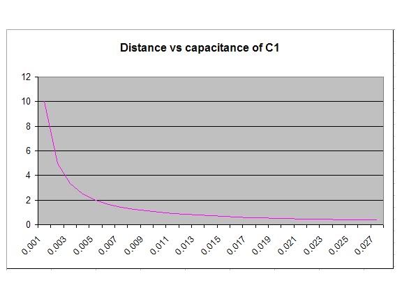
5)Because of the decrease in capacitance (C1), with charge kept constant across the combined capacitor of C1 and C2(law of conservation of charge: Charge conservation - Wikipedia, the free encyclopedia ) The capacitance across combined capacitors (C1 & C2) will decrease and the voltage across combined capacitors (C1 & C2) will increase.
6) The rise in potential across C1, will cause a potential difference between C1 and C2, meaning they are out of equilibrium. Because of their tendency towards equilibrium, charge will move from C1 to C2 (the sum of both will always equal the total charge initially in the system). Because there is a conduction path through the load, the capacitors C1 and C2 constantly equalize, and as the plate are separated, a new higher voltage is attained across both capacitor simultaneously. This is shown in the graph below.
Here the values for the capacitors are 10 farads initially, then C1 decreases as discussed. Here we have capacitance of combined capacitor C1 & 2. It starts at 20 farads (parallel reference frame) and as C1 tends towards zero, the total capacitance moves asymptotically towards 10f.
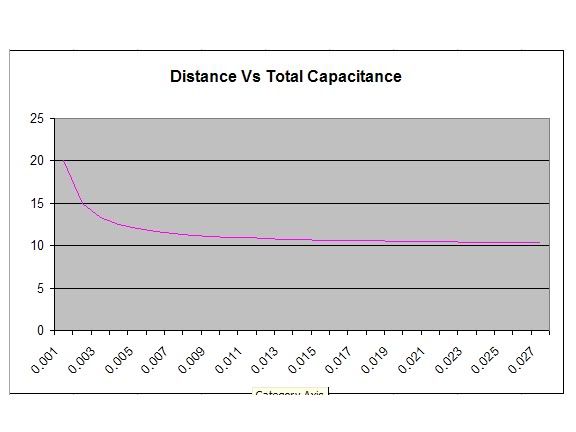
Here is the total voltage across both capacitors. Starting out at 10 volts initial, as C1 tends towards 0, the voltage asymptotically moves towards 20V.

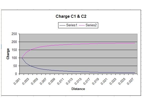
The charge distribution across caps (C1) and (C2) changes with respect to time, meaning charge has moved through the load in the equalization process. With initial conditions of C1= 10 Farads and C2= 10 farads, both have an initial charge of 100 coulombs on each condenser. As the capacitance of C1 (blue line) decreases, so does its charge, while the charge across C2 (pink line) increases. The sum of both at any one moment equals 200, or the initial condition of charge once again satisfying the laws of conservation of charge.
Finally we have the force between the plates of condenser (C1) as a function of distance or time:
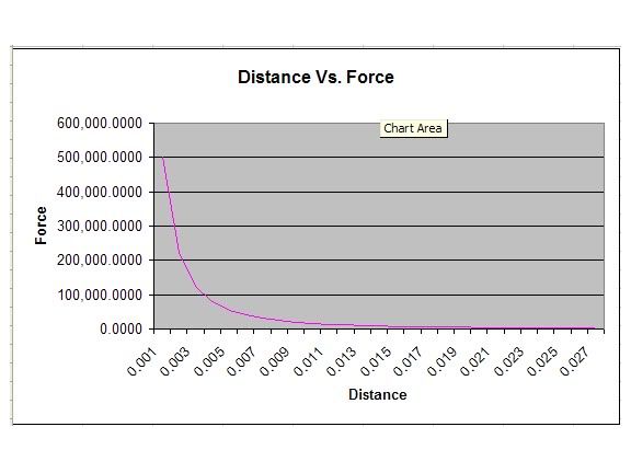
This graph follows the force between the plates of condenser (C1) as they are moved apart and the voltage across both capacitors increases simultaneously. As you can see, while close, there is great force and while they separate, the force decreases. The behavior is that of an exponential decay, much like an inverse square field.
So what does this equate to?
By separating the plates of the capacitor, you have raised the energy of the entire system. In doing so you have caused a finite amount of charge to move across the load for a given time, giving you your power. The force exerted will be given by the integral of the equation for force between the plates, so that we can see the total force required to pull apart distance X.
What is interesting is that while it requires X force to pull the plates apart, they still have a tendency towards moving back together due to the electric forces. -X energy will be exerted by the system returning the plates to their initial position of 10 farads.
Energy to pull plates apart = X
Energy to return to initial state = -X
Total energy = X+ (-x) = 0
For each investment of mechanical energy in the direction of plate separation, the system returns the energy in the next stroke returning to initial conditions.
For each stroke (moving the plates out, or moving the plates in) you move (Y) charge in time (T) where power equals (Y)*(T) = Watt
How quickly the plates can move appart or come together is a function of the TIME CONSTANT of the circuit.
This can be figured out through calculus solving the following KCL equations.


These will solve to give an equation similar to the form of

The heavier the load...the lower the resistance of the load...The faster the time constant.....The more charge moved in less time, equating to more power. Heavier loading = increase in power output.
If the load is an inductor instead of a resistor (perhaps a transformer)....heavy loading on the secondary equates to decrease in reactance of primary = very small time constants = charge moved very quickly = large power output.
If the load is an inductor like a motor. Because charge always stays constant, the motors BEMF is not allowed to cancel any charge via its counter generative properties, hence a standard motors BEMF will no longer affect its operation.
All energy used to cause initial separation of plates, and rise in potential of overall system, will be returned in the subsequent cycle as plates return to initial position and energy state of the entire system decreases. Net input theoretically = Zero
If all input is returned, and each cycle constitutes a movement of charge, in a definite time dictated by the impedance of the load, then the load dictates the time required to complete a cycle, and how much power is developed. Meaning While loading is constant, Time is the only variable consumed
The "heaviness" of the load dictates the time constants, the less the time constant, the more power developed
Put another way, Decrease in time constant = decrease in time domain = increase in possible frequency used. Increase in frequency = increase in power.
Plates can be moved acoustically, through Super Radiance and Phase transition effects, mechanically, etc.
Or
The "Time Machine"
Concept:
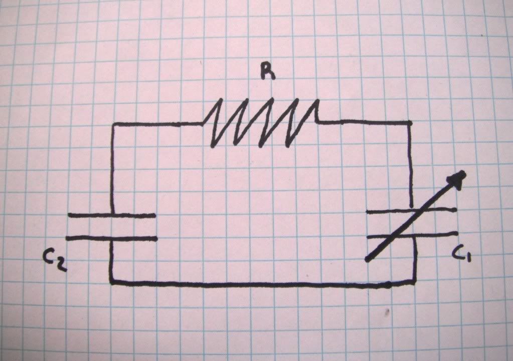
Here can be seen the basic circuit.
C1 = Capacitor having movable platens.
C2 = Static capacitance condenser
R1 = Resistive load (can be replaced with inductive load)
Basic Embodiment:
Initial conditions:
Free Space Permittivity 8.8541E-12
Area Of Plates 1129420269
Initial Voltage (both caps) 10
Charge (C1) 100
Charge (C2) 100
Total Charge 200
C2 Capacitance 10
1) Capacitor 1 (C1) will be a parallel plate variable condenser with movable platens.
2) Connected in series to (C1) will be a capacitor of initially equal value (C2) and resistive load (R).
3) Initially both capacitors will be charged to an equipotential state, so that both have the same voltage across the terminals, and by virtue of having the same capacitance, they will also have an equal charge between them. (See graph for charge distribution)
4) Entering into the time domain, the platens of capacitor (C1) will beg separated, causing a decrease in capacitance via the equation:
As the distance between the plates increases, the capacitance of (C1) moves asymptotically towards zero.
5)Because of the decrease in capacitance (C1), with charge kept constant across the combined capacitor of C1 and C2(law of conservation of charge: Charge conservation - Wikipedia, the free encyclopedia ) The capacitance across combined capacitors (C1 & C2) will decrease and the voltage across combined capacitors (C1 & C2) will increase.
6) The rise in potential across C1, will cause a potential difference between C1 and C2, meaning they are out of equilibrium. Because of their tendency towards equilibrium, charge will move from C1 to C2 (the sum of both will always equal the total charge initially in the system). Because there is a conduction path through the load, the capacitors C1 and C2 constantly equalize, and as the plate are separated, a new higher voltage is attained across both capacitor simultaneously. This is shown in the graph below.
Here the values for the capacitors are 10 farads initially, then C1 decreases as discussed. Here we have capacitance of combined capacitor C1 & 2. It starts at 20 farads (parallel reference frame) and as C1 tends towards zero, the total capacitance moves asymptotically towards 10f.
Here is the total voltage across both capacitors. Starting out at 10 volts initial, as C1 tends towards 0, the voltage asymptotically moves towards 20V.
The charge distribution across caps (C1) and (C2) changes with respect to time, meaning charge has moved through the load in the equalization process. With initial conditions of C1= 10 Farads and C2= 10 farads, both have an initial charge of 100 coulombs on each condenser. As the capacitance of C1 (blue line) decreases, so does its charge, while the charge across C2 (pink line) increases. The sum of both at any one moment equals 200, or the initial condition of charge once again satisfying the laws of conservation of charge.
Finally we have the force between the plates of condenser (C1) as a function of distance or time:
This graph follows the force between the plates of condenser (C1) as they are moved apart and the voltage across both capacitors increases simultaneously. As you can see, while close, there is great force and while they separate, the force decreases. The behavior is that of an exponential decay, much like an inverse square field.
So what does this equate to?
By separating the plates of the capacitor, you have raised the energy of the entire system. In doing so you have caused a finite amount of charge to move across the load for a given time, giving you your power. The force exerted will be given by the integral of the equation for force between the plates, so that we can see the total force required to pull apart distance X.
What is interesting is that while it requires X force to pull the plates apart, they still have a tendency towards moving back together due to the electric forces. -X energy will be exerted by the system returning the plates to their initial position of 10 farads.
Energy to pull plates apart = X
Energy to return to initial state = -X
Total energy = X+ (-x) = 0
For each investment of mechanical energy in the direction of plate separation, the system returns the energy in the next stroke returning to initial conditions.
For each stroke (moving the plates out, or moving the plates in) you move (Y) charge in time (T) where power equals (Y)*(T) = Watt
How quickly the plates can move appart or come together is a function of the TIME CONSTANT of the circuit.
This can be figured out through calculus solving the following KCL equations.
These will solve to give an equation similar to the form of
The heavier the load...the lower the resistance of the load...The faster the time constant.....The more charge moved in less time, equating to more power. Heavier loading = increase in power output.
If the load is an inductor instead of a resistor (perhaps a transformer)....heavy loading on the secondary equates to decrease in reactance of primary = very small time constants = charge moved very quickly = large power output.
If the load is an inductor like a motor. Because charge always stays constant, the motors BEMF is not allowed to cancel any charge via its counter generative properties, hence a standard motors BEMF will no longer affect its operation.
All energy used to cause initial separation of plates, and rise in potential of overall system, will be returned in the subsequent cycle as plates return to initial position and energy state of the entire system decreases. Net input theoretically = Zero
If all input is returned, and each cycle constitutes a movement of charge, in a definite time dictated by the impedance of the load, then the load dictates the time required to complete a cycle, and how much power is developed. Meaning While loading is constant, Time is the only variable consumed
The "heaviness" of the load dictates the time constants, the less the time constant, the more power developed
Put another way, Decrease in time constant = decrease in time domain = increase in possible frequency used. Increase in frequency = increase in power.
Plates can be moved acoustically, through Super Radiance and Phase transition effects, mechanically, etc.


Comment