-
-
Capacitor with two potencials
Hi you are getting into an area that I have been working on for some time, let me explain what I have developed.
Take an aluminium cylinder and place inside a rod electrode in its center, seal the two ends and creat a vacuum inside. Now take another cylinder of bigger diameter and place over the evacuated cylinder.
Now apply a HV+ to the rod in the vacuum (6kv) and connect the negative to the vacuum cylinder. Now apply another HV+ to the outer cylinder (30kv) and the negative to the vacuum cylinder creating a common negative.
Now what do we have, two different environments with two different potencials and a common ground point of separation. Now it will be interesting to see what you think will happen.
Mike
-
Slide 1
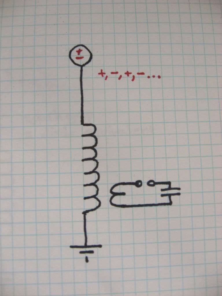
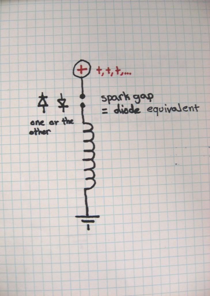
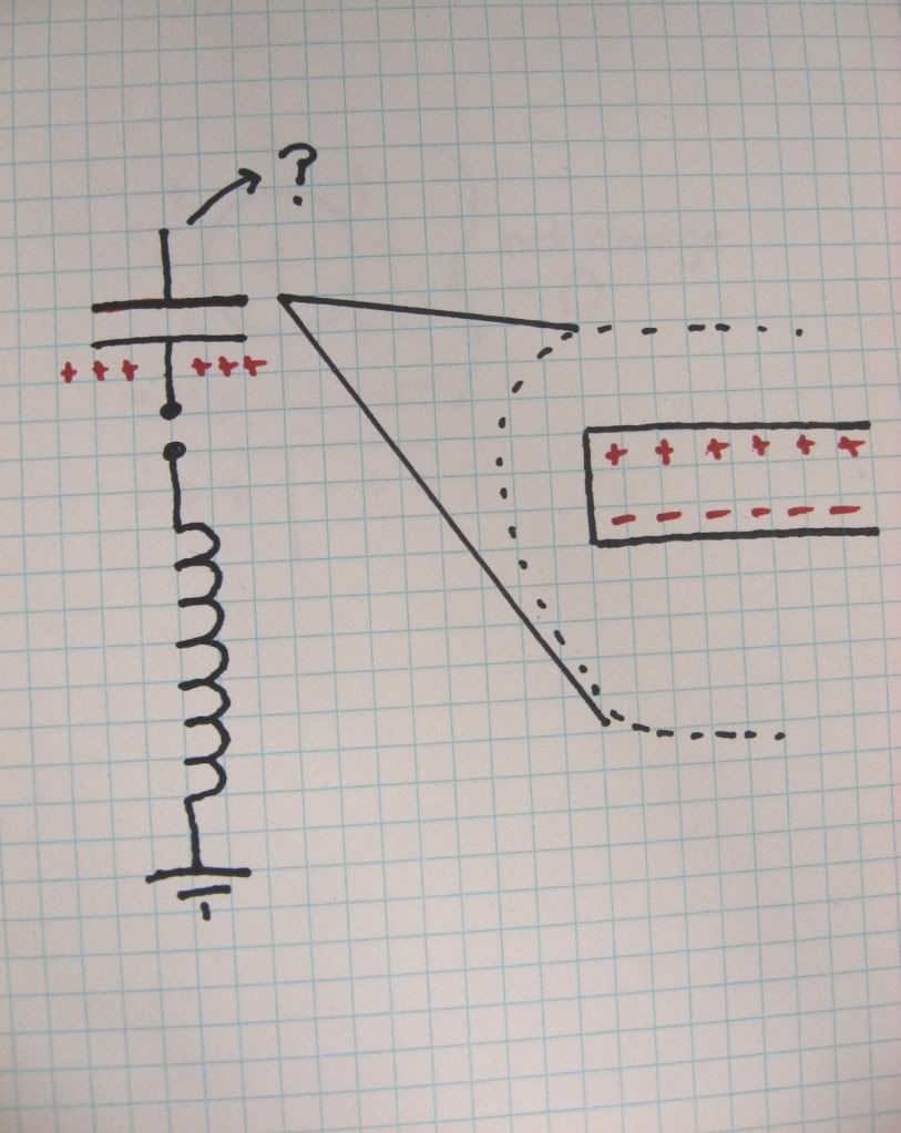
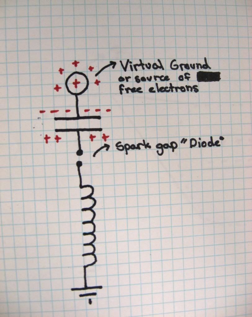
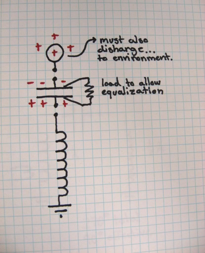
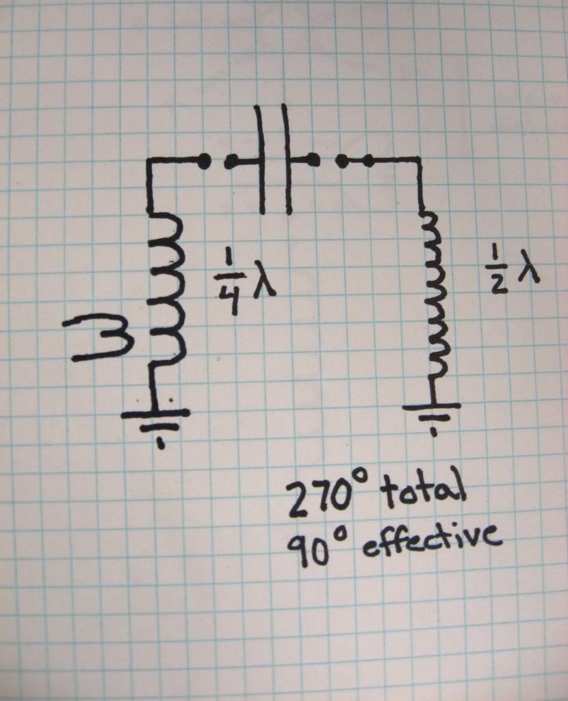
The next slides will be a progression of thought, mostly pictorial, with an explanation.
Last edited by Armagdn03; 06-30-2010, 04:11 PM.Comment
-
-
-
-
-
Slide 6
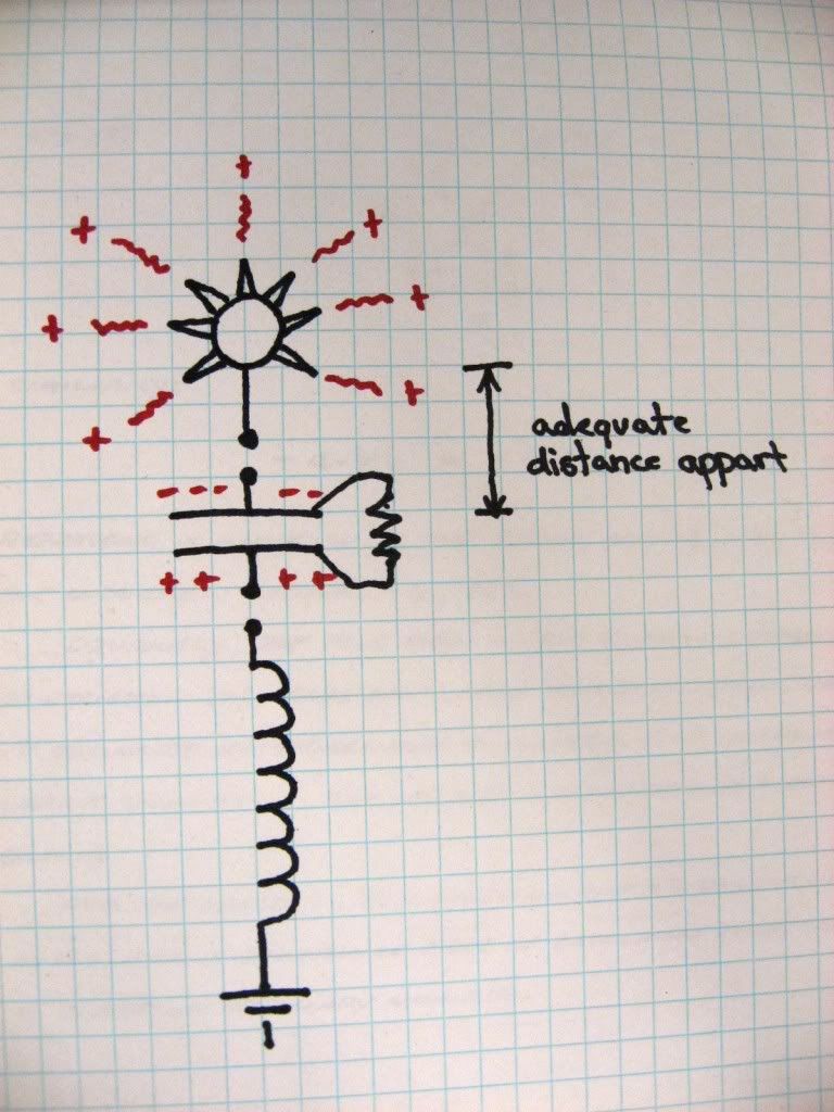
6) In order to keep the second virtual ground, or aerial near neutral, it must itself continually discharge. If sharp peaks are added to it, it will discharge itself rather easily into the local atmosphere dissipating more and more charge as the voltage climbs (which it will, till it reaches a maintained "idling voltage). This allows it to continually either accept or dissipate charge depending on how you build.Last edited by Armagdn03; 06-30-2010, 08:35 PM.Comment
-
Notes:
Notice that possibly the most important aspect of this device is UNIDIRECTIONAL characteristic to the impedance gap. This must not allow any reversal of current.
This device will possibly build up to a steady state. Imagine the first impulse from the primary creating a large surge in the secondary of the Tesla transformer. This surge will pass through the rectifying impedance gap, charging the first plate of capacitor. Simultaneously the impedance gap between the second ground and the second plate of the capacitor will fire. This process will leave the second ground, or aerial sitting at a net charge (either positive or negative). It is likely that this first impulse will leave this net charge on the virtual ground at a relatively low voltage. The next blast from the primary will see an even greater impedance to its unidirectional path because of the charge left on the virtual ground. However the impulse is an inductive collapse by nature (if constructed correctly) and will overcome any impedance. This will boost the virtual ground to an even higher voltage state. This process will continue until the differential between the local atmosphere and the aerial are vast enough to cause easy conduction between them. At this point there will essentially be a solid connection between aerial and atmosphere, creating a good solid "ground" to the air. This will take multiple successive impulses from the primary.
Imagine "Apparatus for the utilization of radiant energy". Instead of receiving energy from an outside source like a battery, the aerial could be of the nature described above, or could be a second apparatus set near this one. The initial impulses from the atmosphere itself, can jump start the system, then you the inventors could figure out what to do with the charge acquired within your parallel plate capacitor.
Reading:
Last edited by Armagdn03; 06-30-2010, 04:47 PM.Comment
-
-
Additional notes:
The primary circuit should be a discharge of a capacitor with the highest practical stored energy into impedance (inductive) of the lowest practical value, through an impedance gap. This means 1-2 turn primary.
The secondary should have very little inter winding capacitance. This ensures that the energy is forced through the impedance gap, rather than into its own inter winding capacitance. We want this to be an inductive discharge which charges our intended capacity (plate one of parallel plate capacitor) and not our parasitic capacities (inter winding capacitance).Comment
-
Comment
-
Erfinder ol Buddy ol Pal!!! Long time no see! I have been on hiatus for a while due to some large life changes, however now i plan to be back in full swing.
Thanks for the comment!Comment
-
Sounds similar to Joseph Hiddink's "One Terminal Capacitor"Originally posted by Michael John Nunnerley View Post

Joseph Hiddink: One-Terminal Capacitor -- Articles & USP#4095162
Joseph Hiddink is still working on his invention 50 yrs later!
Turning a normal 2-terminal capacitor into a single terminal version.Another object of the invention is to provide the means for producing high potentials which can be positive or negative in nature and which are adapted for use in the study of nuclear structure and nuclear reactions.
Still a further object of the invention is to provide a novel and improved means for constuction and operation of a high power particle generator.
Another object of the invention is to provide a novel and improved device for generating potentials of either positive or negative nature of such magnitudes so as to attract, bend or repulse radiation.
Still another object of the invention is to provide novel and improved construction of a device for generation of potentials of either positive or negative nature, to attract or repulse mass.
A further object of the present invention is to provide novel and improved means and its construction for making an inexpensive, yet effective Intense Neutron Generator with possibility for slow to fast neutron emission.
Regards, Mike R.Comment
This forum is preserved as a permanent archive. The community continues at eMedia Press.
- If this is your first visit, be sure to check out the FAQ by clicking the link above. You may have to register before you can post: click the register link above to proceed. To start viewing messages, select the forum that you want to visit from the selection below.

 Tweet
Tweet

 *************
 the good stuff....keep it coming...
Comment