This forum is preserved as a permanent archive. The community continues at eMedia Press.

Announcement

Collapse
No announcement yet.

my smith kanapadz replication

Collapse
X
 
  • Filter
  • Time
  • Show
Clear All
new posts

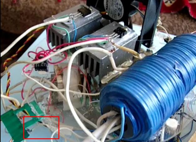
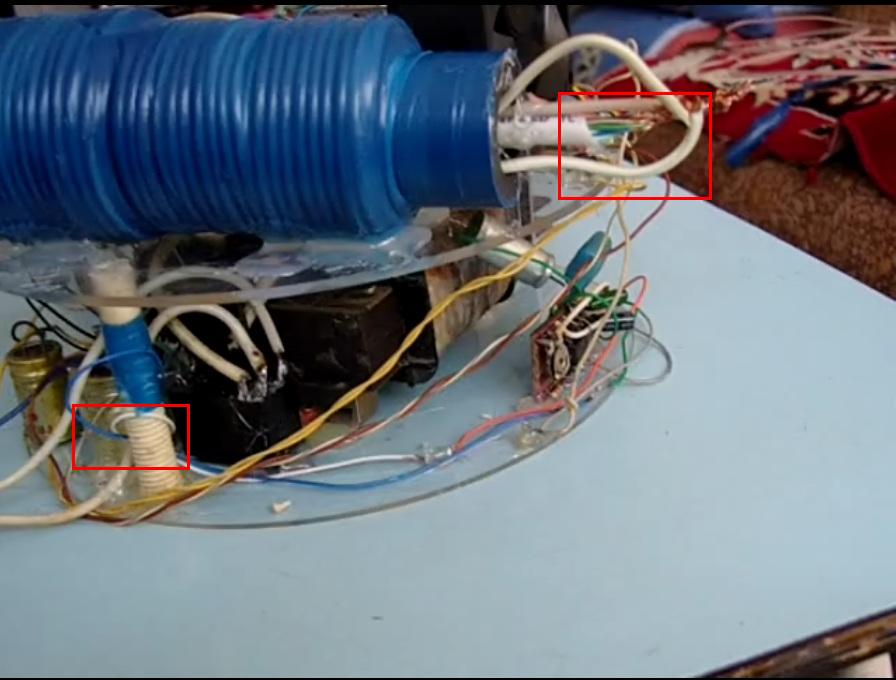
  • For sure it does not look like a pattern. It is a coil. But its function is a big question mark for me.

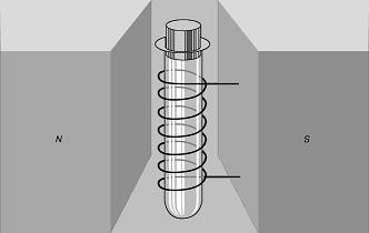
    I was reading today a Nuclear Magnetic Resonance article (yea i am fed up too with it) and it said the RF B-field and the Strong permanent field must be 90 degrees. perhaps this little coil is an RF coil?

    Google Translate

    scrool down to the MNR.


    Perhaps orientation of a supposed RF field does matter, instead of making an imovable RF winding wound with the inverter one.

    EDIT:
    Just to strengthen my theory, i have circled the wire from the spark gap and the wires from the little coil and the big one.
    Clearly the wire from the spark-gap is of the same diameter with the small coil, rather the "transformer" coil's cables.
    Attached Files
    Last edited by baroutologos; 06-25-2010, 07:35 PM.

    Comment


    • Comment


      • Modified SR193 Block Diagram


        Regards,

        VIDBID

        Comment


        • Would you mind explaining more in depth how you came to your diagram?
          Look like a wild mix between Don Smith/Kapagen and SR.
          The 9500 Volt Neon transformer will just shred your spark gap and draw a lot of power.
          SR spoke about a total consumption of 1 Amp at 12 Volt !
          What you are showing there will go way beyond that.

          And why 2 oscillators plus an NST? what is the middle part supposed to do.
          Please be so kind and explain
          Last edited by Xenomorph; 06-25-2010, 08:08 PM.

          Comment


          • Originally posted by luno
            Hi everyone,

            CrazyAlex gives his explanation

            Генератор от CrazyAlex.
            The high voltage part looks like a self oscillating joule thief. Since this is there since april, what's the story behind it. Any success?

            Comment


            • What i might have missed, but the guy talks a lot however i have never seen his SR replication (video) to strengthen his heating theories?

              It is worth reading through all the info there, something might pop up.
              Last edited by Xenomorph; 06-25-2010, 09:34 PM.

              Comment


              • The SST (Smith/SR193/Tesla)

                Originally posted by Xenomorph View Post
                Would you mind explaining more in depth how you came to your diagram?
                Look like a wild mix between Don Smith/Kapagen and SR.
                The 9500 Volt Neon transformer will just shred your spark gap and draw a lot of power.
                SR spoke about a total consumption of 1 Amp at 12 Volt !
                What you are showing there will go way beyond that.

                And why 2 oscillators plus an NST? what is the middle part supposed to do.
                Please be so kind and explain
                You can call it the SST for Smith/SR193/Tesla. I really would not say that it has any Kapagen aspects to it. For one, the Kapagen winding is completely different.

                L3 is the key component. L3 is from Smith who got it from Tesla. The center ground winding of L3 is supposed to produce voltage and current. The winding changes direction after the center tap. The rectifier is supposed to combine voltage and current, but then you have pulsed DC. I suppose there should be a smoothing cap after the rectifier. You need to convert the DC to AC to step it down; hence, the oscillator. The frequency of oscillator should be adjustable. At that point, voltage and current should be combined or infolded. Some of the AC can then be sent to a load, and some of the AC can be stepped down and sent to another rectifier. From there, it can be passed through a voltage regulator. From that point, some of 12vdc goes to the push-pull class AB amplifier, and some of the 12vdc goes to a 12vdc to 120vac inverter capable of powering inductive loads. Notice that there is a variac between the inverter and the neon tube transformer, so you can adjust the voltage across L2 and the gas discharge tube.

                Regards,

                VIDBID

                Comment


                • Comment


                  • Sst

                    Xenomorph, what do you think is behind the SR193 working? Correct me if I'm wrong, but I am assuming that you have been able to get your replication of the SR193 to work yet. If you have gotten it to work, then that is great! If not, then I hope you get it working soon.

                    Regards,

                    VIDBID

                    Comment


                    • Originally posted by luno
                      Hi everyone,

                      CrazyAlex gives his explanation

                      Генератор от CrazyAlex.

                      @cosmo

                      Please translate the writing in the schematic in the above post.

                      Thank you,
                      Don
                      Don

                      Comment


                      • Originally posted by vidbid View Post
                        Xenomorph, what do you think is behind the SR193 working? Correct me if I'm wrong, but I am assuming that you have been able to get your replication of the SR193 to work yet. If you have gotten it to work, then that is great! If not, then I hope you get it working soon.

                        Comment


                        • SR193 HV Module

                          Originally posted by Xenomorph View Post
                          Concerning your last post about the frequency generator module, that is (i must say maybe) the oscillator feeding the HV transformer.

                          SR has stated that he took it from a CFL lamp (!) and that it operated in the frequency range that he deemed alright (25-35 kHz).

                          This by the way is a strong indicator for the fact that this is NOT about some magic frequencies to force transmutation.
                          I think you are right about it being an HV driver.


                          And maybe a CFL circuit can be used or modified to be used as the Frequency Generator Module.

                          Regards,

                          VIDBID

                          Comment


                          • Clearer Image

                            Here's a clearer image.


                            Regards,

                            VIDBID

                            Comment


                            • 12vdc CFLs

                              I found a website that offers CFLs that run off of 12vdc and found one rated at only 5 watts.

                              Regards,

                              VIDBID

                              Comment


                              • 12v and 1 amp Fluoro-Lamp Driver

                                I found lamp driver rated at 12v and 1 amp.


                                Regards,

                                VIDBID

                                Comment

                                Working...
                                X