Announcement

Collapse
No announcement yet.

Nikola Tesla's bifilar coil for Electromagnets Experiments

Collapse
X
 
  • Filter
  • Time
  • Show
Clear All
new posts

  • Nikola Tesla's bifilar coil for Electromagnets Experiments

    Hi all, I have been making some more experiments and am now focusing on Tesla's bifilar coil.

    Have been observing some interesting results, with 18 awg. copper clad speaker wire used for bifilar coils.

    Using 1-1/2" diameter pvc plumbing pipe as coil former, total coil former length is 11 inches.

    First layer of speaker wire is the primary oscillator bifilar coil (double series winding), wired per Nikola Teslas patent.

    Second layer is the secondary bifilar coil, also wired per tesla's patent, using the same type of speaker wire (smaller gauge if needing higher volts output).

    Adjustable stingo oscillator is used to pulse the primary coil, with provides very low duty cycle and sharp pulses to primary bifilar coil.

    This regular solenoid style coil former, seems to work just the same as the pancake spiral version.

    However, since this version of solenoid style coil former, uses less wire than my previously tested pancake coil version, it attains higher frequency,

    which probably gets it closer to resonance.

    By adjusting the oscillator, at a certain input level, when the secondary coil is then placed under load using a 12 volt led bulb,

    the input current is not affected negatively in any way, while the led bulb burns brightly.

    Any thoughts, ideas or experiments that others here may like to share, please feel free.

    peace love light


  • #2
    Hi, just realized, i wound the secondary bifilar coil in the opposite direction, i didn't intend to, it was a normal bifilar, two layer coil,

    though i cut one end and made the coils separate and distinct primary and secondary.

    And just realized, that means the top layer is wound in opposite direction, if that makes a difference to results, i'm not sure.

    Comment


    • #3
      also, you can do 2 windings around the perimeter of the bifilar coil, to be the primary, like in patent 593138. i never could observe any advantage of a bifilar primary.

      also, skim through this modern patent by a guy named Hively, it describes how a bifilar coil, connected in the middle so the magnetic field cancels out, it can act as an antenna to transmit or receive 'scalar longitudinal waves' (SLW), as the author calls it - like pic shows.

      Scalar-longitudinal waves (SLWs) may be transmitted and/or received. A first apparatus configured to transmit and/or receive SLWs may include a linear first conductor configured to operate as a linear monopole antenna at a first operating frequency. The first apparatus may include a tubular second conductor coaxially aligned with the first conductor and an annular balun configured to cancel most or all return current on an outer surface of the second conductor during operation such that the first conductor transmits or receives SLWs. A second apparatus configured to transmit and/or receive scalar-longitudinal waves may include a bifilar coil formed in an alternating fashion of a first conductor and a second conductor such that an electrical current in the coil will propagate in opposite directions in adjacent turns of the coil thereby cancelling any magnetic field so that during operation the coil transmits or receives SLWs.


      i'm still trying to piece together what that means. it might mean you can oscillate it at any freq to send AND receive SLW with such a bifilar. without any primary. so youd test it by sending on one coil, see if a matching coil receives the same signal, wirelessly, but you need some small oscilloscope for that.

      otherwise, i'd expect one needs to add capacitance to the primary circuit, to get the primary resonance freq (removed away from secondary) to match that of secondary, AFAIK thats the way to get the LMD action, is to make it a tesla coil with a resonant primary. have fun!
      You do not have permission to view this gallery.
      This gallery has 1 photos.

      Comment


      • #4
        Hi cold3lectric​, thanks for the reply.

        I will research the things you shared, looks interesting.

        The setup i'm working with can also be tuned, so that when under the led bulb load on secondary bifilar, the input current drops quite a bit.

        Though that may not be ideal for power transfer efficiency, which is why i've tuned it to have as little effect on input current as possible, meaning neutral.

        Again, one and all, feel free to share any findings based on these bifilar coils, wired tesla style.

        I will continue experiments and share results and at some point share pics and schematics, as to exactly what circuits i am using to observe these results.

        peace love light

        Comment


        • #5

          cool! I take it you've come across Master Ivo's bifilar pancake content on YouTube? I got 'started' by reproducing the solid-state tesla coil driver PCB circuit he made, definitely could make kilovolts and plasma. but as you already brought up, the trickiness of even measuring the 'power transfer efficiency

          So i went bananas, and put together a system of 'single wire power transmission' (from one bifilar pancake tesla coil - the sender aka transmitter aka Tx, to another matched bifilar pancake TC - the receiver aka Rx). Mostly cuz I got obsessed with measuring some sort of provable power number. Ended up making a pretty stout vid about it, wanna peep? its from 2024, and lately I've got some even wilder huge helical 'open frame' helical coils, after Dollard.

          The cool thing to me now, is how I used to connect one side to the other, across the toploads, the high voltage output part, and that was the one wire. then learned that the freakin ground wire bottom parts can be connected, and that can be the one wire, totally identically effective. the ground wire is plugged into the resonant connection. and the transmission line is not even a high potential line. it's not even needing to be using the high voltage through the wire, as long as each side's secondary top end is independently high voltage. mind was blown.

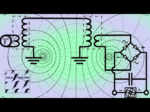
          ANYWAY thats very very specific, but wanna see my little circuit diagram? The circle part on far left with a "negative" spike in it, is the driver circuit making very short negative voltage impulses, and those connect to the tesla coil primary coil capacitor circuit. and on the other receiver side down the line, instead of a driver circuit, it powers a simple low voltage lightbulb or something basic, which can FINALLY be measured for power, definitively. Next step, look at power supply input watts, detect output watts, divide latter by former to get 'transmission efficiency'.

          IMG_0491.jpg

          even though I cannot yet do better than 50%, it's now a metric I can watch while trying different stuff and seeing how exactly it gets improved. fun, if you can believe it

          (this linked video is part II, there's also a part I where I just set it up and do a test powering it through a fluorescent tube as the transmission line hehe).
          Attached Files
           

          Comment

          Working...
          X