If this is your first visit, be sure to
check out the FAQ by clicking the
link above. You may have to register
before you can post: click the register link above to proceed. To start viewing messages,
select the forum that you want to visit from the selection below.
I'm curious as to the CT capacitor in your "the circuit.jpg". Is that capacitor there to adjust the resonance of the secondary of the NST, or is it there to adjust the resonance of the primary of the step-down? I know its there to match the frequencies of the NST with the step-down, but it looks like in the circuit that it is adjusting the resonant frequency of the secondary of the NST unless the spark gap does something weird when it fires that I don't understand. And if so, don't we need a capacitor for the primary of the step-down so it will resonate at 30khz also? Damn, I feel like the guy in idocracy trying to figure out time travel.
Hence, the energy increases quadratically to the current divided by the number of times to reduce inductance.
ie in the national energy we have to increase by 10 times.
But so do not be infinity, because the smaller the inductance, the more commensurate with her lead resistance, and this is also dramatically affects the parameters of the system ..
This of course is different from Zilano's 10kw device where the added "copper coated welding rods" inserted into the primary of the L1 increases the inductance.
Zilano's circuit is a mixture of Dynatron, Don Smith and SR123(?) circuits but has not been posted yet.
Part 1 components and materials 1) High Voltage Power Supply 3000V 100 - 200 watts.
You can use transformers for neon lamps, or any similar
amateur design with a high conversion efficiency and stabilization
output current.
A possible embodiment of the transducer assemblies
2) Permanent link to download the original file:
Youtube Videos:
Cheers Mike
ps created a PDF of Dynatrons Circuit Design (Google Translated) attached
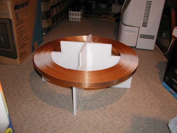
Yes I remember the 5 turns CW and 5 turns CCW center tap to ground bifilar coil L2 secondary windings, 16mm (0.63" or close to 5/8" wide) secondary flat copper strap.
You mentioned 4 turns per 1" for the secondary? 0.63" wide can only fit 1 turn per inch?
A) Do you wind your 5 turns secondary this way?
B) Or do you wind the secondary this way, flat spiral?
well i just went for the required output voltage to suit me so i used caps or diodes or resistors or chokes for the 250 volt range saving me lot of costs. cheaper is better. i was striving for cheaper.
thats where 5 turns counts.
and there are many ways to get the required output. and wot we need is just frequency matching even a voltage lesser than 120 volt will work and even we can bypass spark gap and derive power. we can use solid state tesla coil the don way and can use ferrite rings also so we can use lesser voltage but we have to use high frequency in 200 to 300 khz or 1 mhz. we can use crystal oscillator and as we move to mhz the coil length becomes smaller....... am trying now small footprint but powerful device which can be initiated by just 3 volts pencil lite or AA BATTERIES. SINCE DONS ARRANGEMENT IS AIRCORE THATS WHY WE NEED TO FEED HIGHER AMPS TO GET HIGHER AMPS BUT IF WE GO FOR LOW VOLTAGE AND HIGH FREQUENCY WE STILL CAN GET AMPS BUT WE MUST USE FERRITE CORE.
DON WAS NEVER WRONG.....
REGARDS
ZILANO ZEIS ZANE
Hi Zilano
So you wound your 16mm coil by way of #A (spiral) or #B (flat spiral) in the photos above?
Don showed the way of Tesla! Looking forward to your AA battery design!
use secondary 4 times of primary length in feet.USE BIFILAR
Do you mean:
Primary ________ |----------------| ___ = X
Secondary _________ |--||--| _______ = X/4
Won't that give us a resonance at a 1/4 harmonic of the primary? We would still have to use caps right? Changing the lengths and size of the wire will not make them resonate at the same frequency. Example:
Primary: 246/.03 = 8,200 feet (for 30khz)
Secondary 8,200 / 4 = 2050 feet which gives us 120khz resonance. We would need caps to bring it down to 30khz. Unless the trick is to use a harmonic of resonance of the primary.
"In light of recent events become evident by the fact that we use wires to the pump systems are "superconductors" of particles Left and right twist. It is also apparent is the ability to operate with these particles by means of the resonance properties of electrical circuits in which they (the particles) are circulating. Thus it becomes possible to assemble the chain, the loss of which would be many times smaller than conventional circuit, but due to the resonance coil, absorbing of increases (response of the medium) as the potential for each group of particles, and further, these particles must correctly (right and left twist) dock for an electron with total energy potential. This is my personal view, frailty is evident, as the pilot promotion."
"Not electrons. According to some friends (I also am a supporter of this idea), the electron is a doublet consisting of (at least) two particles, each of which has its spin (vector "orientation"). Being together, these particles and form an electron. Particles doublet have representatives - one of the electric field, the other - the magnetic field. Being a doublet, each particle individually is at rest."

 Tweet
Tweet







Comment