This forum is preserved as a permanent archive. The community continues at eMedia Press.
Announcement

Collapse
No announcement yet.

Donald Smith Devices too good to be true

Collapse
X
 
  • Filter
  • Time
  • Show
Clear All
new posts

  • Thanks Dragon!!

    Nice Information!!

    Comment


    • Originally posted by Slovenia View Post
      Dave,
      I'm not an electrical guy but I've done a lot to help this thread even so. Anyway, not all are that helpful here but everyone wants to be fed. I have learned a lot; mostly self taught; but have a lot to learn yet. I help where I can. I want one of these generators really bad. Your diagrams are very pretty, but we could use more electrical expertise here in the way of help and not criticism.
      Best Regards,
      David Fine / Slovenia
      Your right David, I apologize
      I know what you have been doing is very time consuming and youv done an excellent job.
      dave
      Half of the Answer is knowing the right Question

      Comment


      • Measuring L on Iron Core

        Hi everyone. Thanks for all the tips on my previous post. I have a new challenge. I just got my 3kVA iron core and I'm trying to take an inductance reading.

        My little LCR meter takes readings at 100Hz 120Hz, 1kHz, and 10kHz.

        So I took my first reading of the L1 on the trafo at 120Hz thinking that was "brilliant" cause that was exactly what I wanted! I took the value of L and computed the value of C @ 120Hz by setting the XL and XC equations to each other like I did when calculating the tuning caps for my primary and secondary coils.

        I got suspicious when I saw that the computed value of C was pretty close to the measured value of C.

        Then I realized I really needed to take the L and C measurements at the frequency that it will *see* coming from the upstream circuit. For my setup, that's 35kHz. It took me a while to grok that. But I get it now.

        I saw a post about how to measure the inductance of a coil using a signal generator, but I'm seeing that to get it really precise, I need to hook it up to my L2 and I need my L2 to generate a really smooth signal at an even voltage.

        So I'm back to tuning the L1 and L2, which I still haven't done effectively yet.

        And I'll need to put some form of voltage control on what's coming off of the L2. Or I'll have to find a way to drive the L1 with a very smooth signal, but I'm kind of leaning toward the former approach (controlling voltage off the L2) because I think the disruptive discharge is important.

        And really, before I do any of this, I need to a HF filter line filter between my NST and the wall and I need a HFHV filter between my NST and the spark-gap / tank circuit protect the secondary of the NST from high-frequency kickback. So I ordered a line filter and parts for a Terry Filter from eBay, which a lot of tesla coilers seem to like.

        And I also need a way to make my spark gap quieter because it's *too damn loud*, so I guess I'm gonna build a series spark gap.

        Free energy sure ain't free. :-)

        Can anyone suggest some shortcuts? Am I thinking about this correctly?

        Thanks!
        Last edited by jharmon; 02-08-2012, 03:17 AM.

        Comment


        • Thanks!!

          Thank-you Dave!!! I appreciate your apology very much. It's been very time consuming work, but it has helped me learn a lot while doing it. So, that has been really good for me.

          Originally posted by Dave45 View Post
          Your right David, I apologize
          I know what you have been doing is very time consuming and youv done an excellent job.
          dave

          Comment


          • AC Driven Spark Gaps Disrupts Resonance of Secondary?

            I have been thinking this, but just saw it on the richieburnett site, so i'm even more worried now...

            Static spark gap analysis

            --quote--
            In a TC supplied by AC the static gap firings tend to collect in clusters around the peaks of the supply current. This is because the tank capacitor recharges fastest when the supply current is near the peak of a cycle, and the breakdown voltage is reached in less time. In practice the firing of an AC supplied static gap system is almost always irregular, and it is quite difficult to set up the system to fire regularly over several cycles but it can be done. In terms of performance this irregular firing does not appear to hinder spark growth although it does give rise to poor power factor of the system as a whole.
            --quote--

            Will this totally f my secondary resonance? One argument is... yes. The other is no... the gap won't fire again until the primary and secondary ring out, so it doesn't matter when the next pulse comes. And 35khz is way higher frequency than 120Hz so my downstream trafo won't even notice either.

            Thoughts?

            Comment


            • I don't see any
              iron cored isolation transformer or substantial capacitance at or near the
              output, nor is there an inverter circuit to make clean AC.
              What are the claims of this circuit ?

              I wonder if the circuit designer has tested the circuit and shown the results.
              Does it produce a square or sine wave AC output

              I hope it helps

              Regards
              JJ
              Last edited by myenergetic; 06-22-2012, 07:45 AM.

              Comment


              • Originally posted by Blacktail View Post
                Hi all,
                What does CCW means ?
                Thanks in advance.
                Cordially.
                Welcome Blacktail!
                see post #2128 http://www.energeticforum.com/175108-post2128.html
                And read the new 75 page Utkin paper mentioned above. It explains a lot of effects used in different schematics. Looks very cryptic and misleading if we we read it with our standard knowlege - but it's true.
                Most replications (or trials) make use of more than on effect at same time. They interact like gears and Utkin helps to identify them.
                rgds John
                Last edited by JohnStone; 02-08-2012, 08:37 AM.
                Experts spend hours a day in order to question their doing while others stopped thinking feeling they were professionals.

                Comment


                • Originally posted by soundiceuk View Post
                  Magnetic Amplifiers
                  ....
                  A megnetic valve! Sophisticated but itselve no OU.
                  It is what I see in those Russian circuits producing 50Hz directly.
                  After setup tuned well (i.e. Utkin paper page 60-62) (valve opened) -> they add a coil with mains frequency in order to operate that magentic valve.
                  That giant OU power station is readily prepared to accept us modulating power flow - and there are no heat losses added.
                  Last edited by JohnStone; 02-08-2012, 08:35 AM.
                  Experts spend hours a day in order to question their doing while others stopped thinking feeling they were professionals.

                  Comment


                  • So the mag amp can be used to modulate the output frequency? I really need to research more about mag amps.
                    Last edited by kalena555; 02-08-2012, 09:03 AM.

                    Comment


                    • Latest Utkin file http://dnp.s3.amazonaws.com/b/b2/VladimirUtkin.pdf
                      Whatever you can do,or dream you can,begin it.Boldness has genius,power and magic in it.Begin it now.

                      Comment


                      • Originally posted by JohnStone View Post
                        Welcome Blacktail!
                        see post #2128 http://www.energeticforum.com/175108-post2128.html
                        And read the new 75 page Utkin paper mentioned above. It explains a lot of effects used in different schematics. Looks very cryptic and misleading if we we read it with our standard knowlege - but it's true.
                        Most replications (or trials) make use of more than on effect at same time. They interact like gears and Utkin helps to identify them.
                        rgds John

                        Thanks i just download the latest VladimirUtkin file

                        Comment


                        • Circuit diagram

                          Originally posted by Farmhand View Post
                          Hi Blacktail, CW means clockwise and CCW means counter clockwise, When
                          looking at a coil from the top/bottom/end the CW and CCW winds are opposite
                          wound. Clockwise a right coiled winding Counter clockwise is left coiled.

                          Most of these circuits are dubious and I am unaware of anyone showing more
                          output than input. The particular drawing you showed looks like it has a home
                          wound HV coil supplying a step down transformer, then output. I don't see any
                          iron cored isolation transformer or substantial capacitance at or near the
                          output, nor is there an inverter circuit to make clean AC.

                          What are the claims of this circuit ?

                          I wonder if the circuit designer has tested the circuit and shown the results.
                          Does it produce a square or sine wave AC output ?

                          Furthermore I don't think people should be promoting the dubious and
                          untested work of other people who have nothing real to show. Especially
                          those who cannot explain what they are promoting. Just my opinion.

                          Cheers
                          Hi Farmhand,

                          That diagram is pulled out of chapter 3 of my eBook and is shown out of context (without my permission and technically, in breach of my copyright, as Zilano was fond of doing). It is one step in the chain of showing newcomers possible high-frequency high-voltage power supplies, explaining resonance between L1 and L2, showing a POSSIBLE physical layout, discussing spark gap types, discussing capacitor types, modulation and step-down to local mains frequency and voltage, all under the proviso that I am NOT an experienced builder. The diagram was pulled out of the middle of that explanation sequence which is intended to encourage people to join this thread on this forum which some background information already in hand as searching through 90 pages of posts is very time-consuming and can be quite confusing - it took me several hours solid when I came to this thread a month ago.

                          And yes, you are quite right, the circuit is unproven, coming from a former forum member called Zilano, but as a starting point, it seems as good as any, being consistent with Don Smith and Tesla as far as I can tell. But, you need to understand that while you are expert in electronics and have a substantial long-term familiarisation with the efforts and discussion of the members of this forum, the situation is very different for many other people who need encouragement and some idea of possible forms of physical construction, while being made very aware of the substantial dangers of a capacitor charged to high voltage, and so the basic facts need to be stated very clearly and simply.

                          As to the Valdimir Utkin document, Vladimir passed me a minor revision late last night, there should be a further update later today. I will put a revision date on the website, but if there is a major upgrade, I will mention it on this forum. The latest version is always under the same link: Energetic Forum - Forum Display free-energy-info.com/VladimirUtkin.pdf

                          Patrick K.

                          Comment


                          • Thanks Patrick

                            Thanks Patrick for your continuing input and contributions here. It was by discovering your site in 2007 that made me aware of all the possibilities in
                            the free energy arena. I did not find this forum until 2010. I wish I had found
                            it sooner.

                            George

                            Comment


                            • Also not to be forgotten in the conversion and adaptation is the Kacher / Brovin circuit and its variations here is a brief explanation of its operation

                              Brovin / Kacher Generator (Invention and Operating Principle) - YouTube
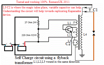
                              You will see an immediately similarity to the basic circuit that Mr clean sketched out for us This is Romero's take on the Kacher circuit also using an AV plug which may bring one of ZZZZs circuits to mind .. however this ones well tried and tested!


                              which is using either a flyback coil or in a later version a Tesla coil kacher driver per Romero circuit.MPG - YouTube
                              Last edited by Duncan; 02-08-2012, 01:42 PM.
                              Whatever you can do,or dream you can,begin it.Boldness has genius,power and magic in it.Begin it now.

                              Comment


                              • Re Romero 2011 working ou

                                I think this circuit looked good to the meters, but was actually not ou.
                                Apparently the batteries died after a week or so. R is suggesting the use of capacitors.
                                When you do this type of circuit, you should switch the device off for 15 minutes and then measure the battery voltages. Even then it's not sure you have gain because battery voltages go up in a heated room and also in light.
                                So it has to be tested over a few days at least. It looks like a good experimental circuit though and definitely worth experimenting with.
                                At last experimenters are beginning to understand the value of resonance, which is hard to attain in practice.

                                Comment

                                Working...
                                X