This forum is preserved as a permanent archive. The community continues at eMedia Press.

Announcement

Collapse
No announcement yet.

Big Joule Theif

Collapse
X
 
  • Filter
  • Time
  • Show
Clear All
new posts

  • Tectalabyss
    replied
    Sounds great

    Originally posted by Vaporizer View Post
    Hi all,
    I'm getting behind. Haven't felt the best.

    @ Jbignes5,
    I'd say if you reverse the scope leads the wave will invert and be back on top.

    I did my test with the 2 3/8" 16 turns 26ga 8 turns each side. 1.5v adjusted for the brightest LED across the E-C. It was really bright and then went dim. Hmmm..TIP31C, changed it even though it shouldn't have blown. Still dim...
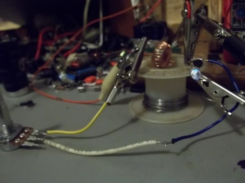
    Changed the LED and it had blown it so I figured it was just a weak one. Nope, 2nd one blew too. Ok, enough is enough so I put 10 on it. Still very bright and 12 is all I had of the 12,000mcd 5mm white. I have never came close to blowing an LED at that connection point before. That toroid has no secondary winding either. All were with smaller toroids though. So, it cruises nicely with 12 and draws 265ma @ 1.25v. I ordered 50 white 140,000mcd that have a stated draw of 20-30ma. The 230,000mcd LEDs were rated at 300ma ea. Hmmmm sounds like not so good a choice so I passed on them.


    eaby has the same 2 3/8" toroids I bought up again. They are from Valley Surplus. 10 for $9.99 + 9 S&H. If you win it comes out to $2 ea. I saw 2 postings. I figure they can't be to bad if the can blow the LED thats supposed to be protecting my transistor. lol
    @Vaporizer.
    Sounds like you are on to something! I bet with the right secondary you could make some volts I've never tried that type transistor before? Thats why I use a variable resistor I can start with one led and increase slowly and leds till I get to the limit.(Thank Lidmotor for that )Ideal(.Opps I Think you did use a variable resistor sorry) I Hope you get to feeling better. Keep us posted.Tec
    Last edited by Tectalabyss; 12-10-2010, 01:00 PM.

    Leave a comment:


  • Jbignes5
    replied
    H,,,...

    Originally posted by Vaporizer View Post
    Hi all,
    I'm getting behind. Haven't felt the best.

    @ Jbignes5,
    I'd say if you reverse the scope leads the wave will invert and be back on top.

    I did my test with the 2 3/8" 16 turns 26ga 8 turns each side. 1.5v adjusted for the brightest LED across the E-C. It was really bright and then went dim. Hmmm..TIP31C, changed it even though it shouldn't have blown. Still dim...
    Changed the LED and it had blown it so I figured it was just a weak one. Nope, 2nd one blew too. Ok, enough is enough so I put 10 on it. Still very bright and 12 is all I had of the 12,000mcd 5mm white. I have never came close to blowing an LED at that connection point before. That toroid has no secondary winding either. All were with smaller toroids though. So, it cruises nicely with 12 and draws 265ma @ 1.25v. I ordered 50 white 140,000mcd that have a stated draw of 20-30ma. The 230,000mcd LEDs were rated at 300ma ea. Hmmmm sounds like not so good a choice so I passed on them.


    eaby has the same 2 3/8" toroids I bought up again. They are from Valley Surplus. 10 for $9.99 + 9 S&H. If you win it comes out to $2 ea. I saw 2 postings. I figure they can't be to bad if the can blow the LED thats supposed to be protecting my transistor. lol
    When I said it was backwards i mean the hump went left. The h is reversed. Also I fried an led when I changed from the captret to nothing in between the dead 12 gel cel that has 9 volts on it. Rofl.

    I went back to the small torrid and I believe the trannie was controlling over 60v. This is with a single bifiliar torrid.

    The one problem that I see with the captret it blocks the feed back to the battery. Thats why I dropped the captret for now.

    Leave a comment:


  • Vaporizer
    replied
    Hi all,
    I'm getting behind. Haven't felt the best.

    @ Jbignes5,
    I'd say if you reverse the scope leads the wave will invert and be back on top.

    I did my test with the 2 3/8" 16 turns 26ga 8 turns each side. 1.5v adjusted for the brightest LED across the E-C. It was really bright and then went dim. Hmmm..TIP31C, changed it even though it shouldn't have blown. Still dim...
    Changed the LED and it had blown it so I figured it was just a weak one. Nope, 2nd one blew too. Ok, enough is enough so I put 10 on it. Still very bright and 12 is all I had of the 12,000mcd 5mm white. I have never came close to blowing an LED at that connection point before. That toroid has no secondary winding either. All were with smaller toroids though. So, it cruises nicely with 12 and draws 265ma @ 1.25v. I ordered 50 white 140,000mcd that have a stated draw of 20-30ma. The 230,000mcd LEDs were rated at 300ma ea. Hmmmm sounds like not so good a choice so I passed on them.


    eaby has the same 2 3/8" toroids I bought up again. They are from Valley Surplus. 10 for $9.99 + 9 S&H. If you win it comes out to $2 ea. I saw 2 postings. I figure they can't be to bad if the can blow the LED thats supposed to be protecting my transistor. lol

    Leave a comment:


  • Jbignes5
    replied
    believe it or not....

    Originally posted by xee2 View Post
    @ Jbignes5

    Nice scope shots. Perfect Joule thief waveform. I am surprised you are able to get the Joule thief to work from the capacitors. Good work. What transistor are you using? The MPSA06 seems to work well at low currents.
    The package says 2222a... I'll have to get me some MPSA06 then because the torrid I wound just isn't enough to fuel itself yet. I got another torrid here at about 1 1/2 inches or so and I'll wind it up tomarrow. I'm just doing the standard JT circuit. Nothing special yet but I am running it through the captret 4 banger I made. I also paralleled the battery with a nice 1000uf 200v cap and I have been filling the cap then taking it off of the battery to see the run times. For some odd reason the JT likes the led on full in order to have the run time be extended. But I get about 30 seconds of run time then it is exausted. Maybe a bigger torrid might give me the oscillation I need to become self sustaining. I am also running it on my dead 12 volt gel cell with about 9.2 volts in it. Because of the Captret I can run it on larger batteries. I have not gotten the results yet but I need the bigger torrid....

    We got buried today in snow... Rofl... Catcha later....

    *edit* After making the big one the h-wave is now reversed? Did I wind it wrong?
    Last edited by Jbignes5; 12-09-2010, 06:37 PM.

    Leave a comment:


  • xee2
    replied
    @ Jbignes5

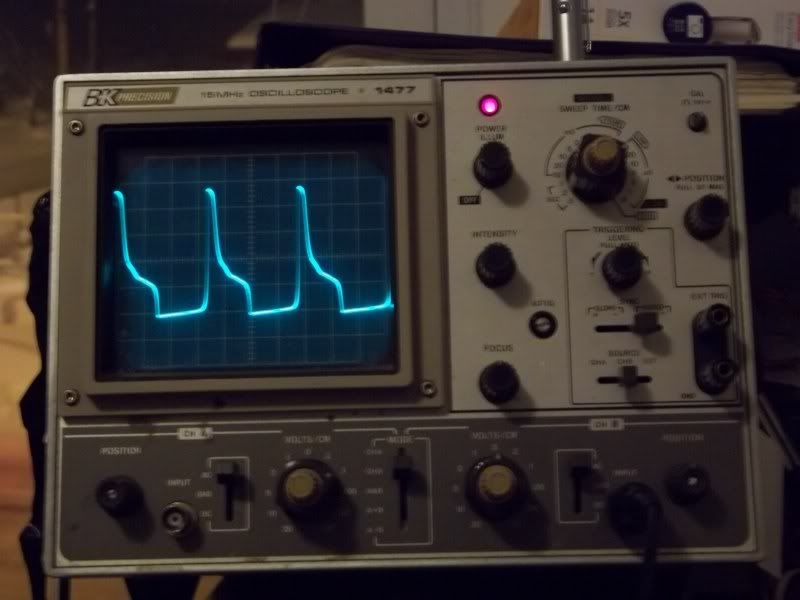
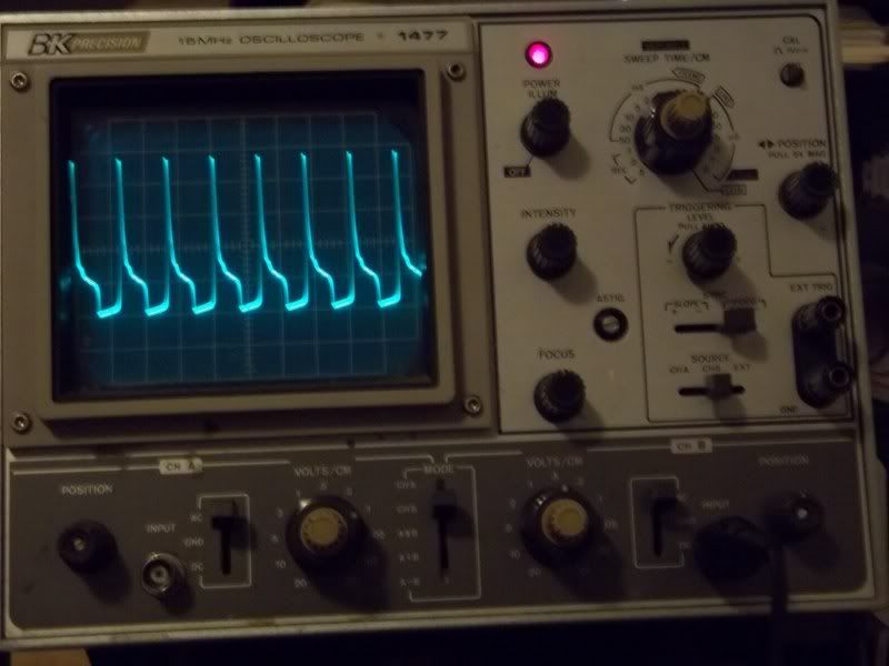
    Nice scope shots. Perfect Joule thief waveform. I am surprised you are able to get the Joule thief to work from the capacitors. Good work. What transistor are you using? The MPSA06 seems to work well at low currents.

    Leave a comment:


  • synchro
    replied
    Funsaver Neon

    Check out my new Kodak disposable flash circuit neon video:

    Leave a comment:


  • Jbignes5
    replied
    Well...

    Originally posted by Tectalabyss View Post
    @Jbignes.
    I'll try that and see.On the transistors I am not sure I've tried some very old and some new one's If you know you JT is working Ok then you can try the C4632's with a 1.5 AA and go up from there.and if the work great.Hope that helps.someone here will know for sure. Thanks Tec
    I am trying to build the unit. I have not built it yet just wanted to know if the trannies would work...

    Also when dealing with the captrets be advised that once in awhile you must short them out entirely. All connections need to be shorted together to bring the strength back up of the captret. It is one thing that keeps me from saying this is an effect that we need to investigate further. Something in there gets built up and needs to be reset periodically.

    Ok I got one running off the captret. Mine is 4 captrets in parallel. A small torrid bifiliar wound, only one pair all the way around. Oh and I can say that adding a magnet does increase the light seen. I had to put some spacers in between the magnet and torrid. If you get too close the light goes out but i also don't have a resistor on the base because of the little real current in the circuit due to the captret. I'll add a variable resistor to it and see if putting the magnet on the coil itself increases the light or makes it go out again.

    *edit* After adding the variable resistor getting the magnets anywhere near the torrid lowers the light...

    I'll add my photo's of the beautiful h-wave i got on my scope.

    And here they are:


    Sorry I don't have smaller ones...
    Last edited by Jbignes5; 12-09-2010, 12:58 AM.

    Leave a comment:


  • Tectalabyss
    replied
    I'll Try that

    Originally posted by Jbignes5 View Post
    One thing to note as well. If you parallel the captrets this flow gets stronger as well. I have done up to 8 captrets in parallel and it give a good amount that way. If turning up the JT decreases the battery then parallel a few more captrets in there and I bet you wont have problems.

    By the way I have a few trannies that I need help with in getting my own circuit up and running. I know they are 1200 volts capable. The model number is c4632. Would those work in the JT? They came from a professional monitor that was burned out. If someone could tell me if they are right for the JT that would be very much appreciated.
    @Jbignes.
    I'll try that and see.On the transistors I am not sure I've tried some very old and some new one's If you know you JT is working Ok then you can try the C4632's with a 1.5 AA and go up from there.and if the work great.Hope that helps.someone here will know for sure. Thanks Tec

    Leave a comment:


  • Jbignes5
    replied
    You are welcome...

    Originally posted by Tectalabyss View Post
    @Jbignes.
    First let me say thank you.I did the test you were right.I also found that if I changed the setting on the variable resistor on the JT it would also change the voltage draw on the battery. I don't have the right equipment to check this setup the right way.But this has been a fun learning experience and still more to learn.Thanks Tec

    One thing to note as well. If you parallel the captrets this flow gets stronger as well. I have done up to 8 captrets in parallel and it give a good amount that way. If turning up the JT decreases the battery then parallel a few more captrets in there and I bet you wont have problems.

    By the way I have a few trannies that I need help with in getting my own circuit up and running. I know they are 1200 volts capable. The model number is c4632. Would those work in the JT? They came from a professional monitor that was burned out. If someone could tell me if they are right for the JT that would be very much appreciated.

    Leave a comment:


  • Tectalabyss
    replied
    You are correct

    Originally posted by Jbignes5 View Post
    Do a simple experiment for me. Hook the captret up alone. Once you get it running with the led over the pos and neg of the cap let it run for a bit. Afdter a small time measure from the negative of the battery to each post of the captret. You will be surprised to find out that each combo of negative (o) on the captret to the other posts have a positive potential on each. Meaning (o) to + of the captret and (o) to the negative. Although the negative is lower in potential then the positive they both have positive potentials. The trick there is the negative of the cap is induced from the positive. Thats because the case to positive is the driver and the (o) to thew negative is the load connection. This induces a flow in the (o) to negative of the capacitor and I do think it is free. But the flow is weaker then the batteries flow. The JT is the way to utilize this weak flow.
    @Jbignes.
    First let me say thank you.I did the test you were right.I also found that if I changed the setting on the variable resistor on the JT it would also change the voltage draw on the battery. I don't have the right equipment to check this setup the right way.But this has been a fun learning experience and still more to learn.Thanks Tec

    Leave a comment:


  • Jbignes5
    replied
    Of course it doesn't match...

    Originally posted by Tectalabyss View Post
    Hello Vaporizer & All.
    I was hoping you could tell me ?? when I tried hooking it up the other way it wouldn't work? If I run it straight to the battery it pops the transistor.If I run it this way the leds are very bright no heat and the battery start's climbing. I just don't know ??? Today has been a good clear headed day so I took advantage If tomorrow is as good I will try and draw a diagram of my mess and post it. If not as soon as I am able. Thanks. Tec

    Do a simple experiment for me. Hook the captret up alone. Once you get it running with the led over the pos and neg of the cap let it run for a bit. Afdter a small time measure from the negative of the battery to each post of the captret. You will be surprised to find out that each combo of negative (o) on the captret to the other posts have a positive potential on each. Meaning (o) to + of the captret and (o) to the negative. Although the negative is lower in potential then the positive they both have positive potentials. The trick there is the negative of the cap is induced from the positive. Thats because the case to positive is the driver and the (o) to thew negative is the load connection. This induces a flow in the (o) to negative of the capacitor and I do think it is free. But the flow is weaker then the batteries flow. The JT is the way to utilize this weak flow.

    Leave a comment:


  • Tectalabyss
    replied
    Theres the rub ?

    Originally posted by Vaporizer View Post
    Hi Tec,
    I noticed one thing right off after reading your hookup description. "pos + from the JT going to the Neg - on the captret", That doesnt match the Dr's configuration schematic. I would think the JT + would go to where his 12v + is.
    Am I missing something?
    Hello Vaporizer & All.
    I was hoping you could tell me ?? when I tried hooking it up the other way it wouldn't work? If I run it straight to the battery it pops the transistor.If I run it this way the leds are very bright no heat and the battery start's climbing. I just don't know ??? Today has been a good clear headed day so I took advantage If tomorrow is as good I will try and draw a diagram of my mess and post it. If not as soon as I am able. Thanks. Tec

    Leave a comment:


  • Vaporizer
    replied
    Hi Tec,
    I noticed one thing right off after reading your hookup description. "pos + from the JT going to the Neg - on the captret", That doesnt match the Dr's configuration schematic. I would think the JT + would go to where his 12v + is.
    Am I missing something?

    Leave a comment:


  • Vaporizer
    replied
    Hi All,
    The link Nick posted Jule Thief is very interesting when looking at just the math portion IMHO.
    I was glad to see the example used the same wire dia for both. If looking at the ratios of windings, L1=4, L2=8, L3=4. So, we have a 2:1 or 3:1 from the primary to secondary depending if you use L1 added to L2 for the math. It results in 7v per L3 turn drawing 80ma from the battery.
    Example 2 L1=10, L2=20, L3=4. Now we have a ratio of 5:1 or 7.5:1 with a result of 4v per turn on L3 drawing 45ma.
    One would initially think example 2 would give a higher output using conventional thinking with straight math. It does have a better ratio for stepping up. It appears the longer wire length, which has more resistance, highly influences the output. No doubt permeability of the core plays an important role here too influencing efficiency.

    I think I have a way to do this test running all the combinations pretty quickly and simply. I'm going to give it a try and if it works I'll post the method with pics.

    The original JT schematics showed a 1:1 ratio(L1, L2), turns varied, but it seems it was more of a "proof of concept" showing it would work. If one plans to not use a secondary this information is still crucial for determining what you want to do with the E-C load. You may want to run 1 or a few LED's in a flashlight for a long time, or you may be looking to use many LED's. Knowing this will determine how you wind for the situation you want to acquire.

    Hopefully this makes sense to more than just me!

    Leave a comment:


  • Tectalabyss
    replied
    Thanks for the update

    Originally posted by Vaporizer View Post
    Hi Tec & all.
    I looked up The Dr's page on the captret.


    I haven't read much on it at all, but I'm struggling to see any significance of the circuit. Is it supposed to raise the battery voltage? On the Dr's page I can see where the cap could get voltage to it , but its flowing through 2 different resistors lowering the current(the LED being one). If the LED does indeed pulse "vlf" as the Dr noted, it should pulse charge the cap, but there is no evident indication of the voltage being raised to a higher potential that I can possibly fathom. Pulsing the cap in this configuration can cause the cap to react differently than normal. Like a battery, but it should not get a higher voltage than the battery. If a potential diff in voltage across the cap is causing the cap to react like a battery, it will develop gas and possibly blow if the reaction is large enough inside the cap.

    All in all, I'd have to say pass on this one. If you do play with it...keep that cap in an open top container in case it does pop & flash.
    Hello Vaporizer & All.
    Thanks for the warning I've seen The big can type go boom and it not pretty we used cap banks at work to help with the amp draw on the soft start for the big hp motors and when they went you had better take cover Ha.My setup is running has been since this morning no heat from the 2N3904 transistor or any where else yet.I tried hooking this same battery to my JT and the first thing to pop was the transistor. I just dont know any Ideals ??? Thanks Tec

    Leave a comment:

Working...
X