

 Tweet
Ok.... I'm going finish with this...
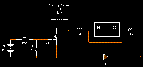
The schematics was corrected, look C1, is like you said me, for resonance with the coil in paralel, so, like in my theory this is not resonance.... Look the first schematics with mosfet and transistor, capacitor is not for resonance, is only a path..... Here the schematic with switch.... Yet if you remove the diode D1, in that configuration you don't get a good HV spike.
With this last schematics is exactly to original when I started this thread, you'll need think if this is resonance really.
Attached Files
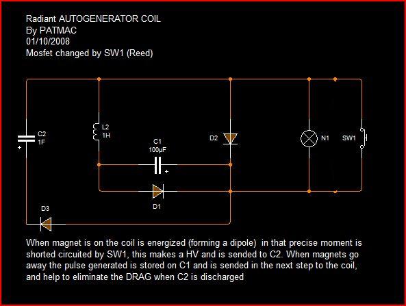


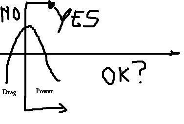
 I wish others would start working on this to try and confirm your results. I have however been having good success with my latest circuit i posted above. It definitely has a resonant effect to it, you need to adjust that C1 value for given rotor speed(frequency) to get the max HV output, while still putting no load on the rotor other than the magnet attracting to the core while its leaving. I believe my circuit will preform very well using a wind mill type generator coil(air core/w strong neo's) that should allow me to have no drag at all in theory since there will be no core for the magnet to attract to while its leaving. I question how well the coil will self induce using an air core, but for now i think this is the direction im going to pursue.
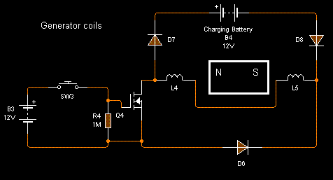
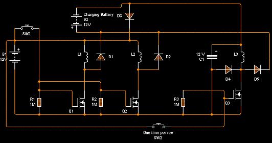
 (That said Bedini), only that is better than traditional setups.
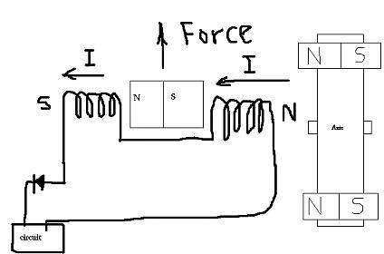
 with hd bearings

Comment