This forum is preserved as a permanent archive. The community continues at eMedia Press.

Announcement

Collapse
No announcement yet.

Gray Tube Replication

Collapse
X
 
  • Filter
  • Time
  • Show
Clear All
new posts

  • Electrotek,
    "... high energy discharge between the first and second anodes is transferred to the charge receiving means ..." Discharge between anodes - HV anode and LV anode, and energy transferred to the grid, it didn't say discharge to the grid. It is exactly the line that caused me to think about tube meaning.
    And it is the best way Gray could explain energy on the load.
    Last edited by mlurye; 02-15-2009, 10:22 PM.
    Mike

    Comment


    • Mike: It also doesn't say "...(some kind of energy within the) high energy discharge between the first and second anodes is transferred to the charge receiving means ..."

      However, statements later in the patent do give this impression. That's why the mechanism of operation is hard to determine from reading the patent.

      Comment


      • Originally posted by boguslaw View Post
        This I posted on alfenergy group


        "The CSET IMO is Tesla magnifying transformer
        with pancake coil(s) inside copper tube. Working in step down mode."

        "To be precise primary of CSET is rather a spiral made of copper sheet,
        just 2 or 3 turns. There are probably few pancake coils inside copper
        spiral connected to it from outside, inner connection done to HV rod.
        Just after pancake coils there is a spark gap with carbon resistor rod
        facing HV rod which does not extend much from coils.It's recreating
        lightning process. Carbon rod is ground, HV rod is cloud, pancake coils
        are like Tesla magnetometer or magnifying transformer. But in this case
        voltage is probably stepped down to thick copper spiral.
        Element 38 is a insulated plate inside motor acting as final one
        terminal capacitor. Element 36 is HF coil with additional transformer.
        Arrows have two meanings: they show current flow and rotary reaction
        inside motor, they also could indicate two currents facing each other at
        90 degrees, and that is what really happens inside this complex element.

        You should have no single problem finding that element in Tesla lecture
        from 1892.It's a complex coil with shifting phase transformer. Two HF
        currents with phase shifted 90 degrees generate magnetic pulse.

        Element 42 is used to discharge cap 16 and to recharge it AT the SAME
        moment, discharging current i normal one, while charging is HF. Charging
        is allowed by diode 44 action. You can easily check that's true with any
        HF current , diode across cap is acting like a gate so difference of
        potential is made."
        Boguslaw: I like your line of reasoning. After you first started talking about this, it occurred to me that maybe the CSET is the high frequency capacitor, at the end of a single wire circuit.

        But I think 42 is a switch which connects the motor's inductive kick to the battery - after the motor is pulsed.

        Can you make pancake coils to test your circuit?

        Comment


        • Thought I'd throw a little something into the mix. Here is a comparison so you can see the old and new circuits side by side. This may give some insight on what Grey was doing or trying to do with the CSET.

          I almost forgot, Here is the other one.
          Last edited by Beshires1; 02-18-2009, 10:47 PM.

          Comment


          • great comparison beshires1!!!

            makes it a lot easier to see whats going on there and compare

            Comment


            • Charging through the grid

              Originally posted by mlurye View Post
              Just as information,
              Gray's Tube ~ Morays Lead and Silver bars ~ Testatica disks. They do play same role.
              And by the way Spark in Gray's tube should NEVER jump from anodes to the grid.
              I have to side with Mike on this. I don't see anything in the patent that even implies that the spark should jump to the grids. If this was the intent, then why are the grids constructed the way they are, with a significant surface area? It either has to be for radiant energy receiving, or to provide a capacitance, or both.

              Originally posted by Electrotek View Post
              The last time I read the patent, it said that the intense discharge between the anodes transfers to the grids and is conducted through the motor. (4661747, column 1, lines 46-48)

              The only way this issue might be resolved is if someone builds a CSET circuit which pops a coil without the grid-to-rod arcing. Or maybe the HERF device in the reference patent (3798461), also without any arcing.

              The only CSET test I've done produced a 1/2" arc between two grids at 7.5 kV, using my voltage doubling diode T-tap.

              I don't doubt that this is a great way to charge a storage cap. It just doesn't look to me like what is described in the patent. Although I haven't popped a coil, I did prove tonight that I can charge a cap from the energy coming off the grid without any arcing to the grids.

              Granted, I only charged a 10uF cap to 20-30V, but it only took a few seconds, and I'm only using a cordless drill battery chopped up through an ignition coil. Given my puny attempt at recreating that effect, I think it's within reason to accept that Gray's motor could have done a much more effective job of charging cap 38 and driving a load. He was using some very powerful supply batteries, a much higher frequency, and I suspect his carefully tuned circuit resonance would make that job a lot easier.

              Just my two cents for this evening. Good night.

              Comment


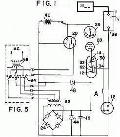
              • 4595975, patent say. Capacitor 16 is charged wit high voltage DC potential. It ain't supposed to do nothing but set there a charging up. Then when the commutator contacts align up it then switches on the low voltage, the capacitor 16 discharges into the tube (Between the anodes , And this high energy pulse is electrostatically coupled to the grids. Pulsing the inductive load (Coils) As the field collapses the BEMF charges capacitor 38 Because the commutator has removed the supplying circuit, and thats the only place for it to go. Capacitor 38 discharges this stored energy into the Battery for recharge purposes. This means that the tube will not work unless the electrodes are spaced to the breakdown voltage of the capacitor. Capacitor 16 discharges into the tube, pulsing the coils, Capacitor 38 discharges into the Battery, Not back thru the load (coils). This is How the tube works. Read Items 20 thru 60, patent 4595975. Without the commutator doing the things it has to do durning this process, the tube will not work.The amount of energy will be preportional to to the amount of time allowed to charge the capacitor and the intensity of the high voltage used to charge the capacitor.
                This is my two cents and is in line with the patent. And quite frankly it should work.

                Comment


                • resonant charging choke

                  Originally posted by Beshires1 View Post
                  Thought I'd throw a little something into the mix. Here is a comparison so you can see the old and new circuits side by side. This may give some insight on what Grey was doing or trying to do with the CSET.[ATTACH]2225[/ATTACH]

                  I almost forgot, Here is the other one.[ATTACH]2226[/ATTACH]
                  I've built several variations of the older one and they all work.

                  In one schematic I posted not too long ago, I showed the resonant charging choke coming off the coil. The output of the ignition coil thru diode through coil then to the cap is a "resonant charging choke". Simply it limits current, which isn't an issue in this case anyway since it is the output of the ignition coil but what is relevant to this is that you get 2 pulses for the price of 1 to the cap and this is one of the reasons the cap charges quicker. One pulse goes through the diode and through choke to the cap.When the choke collapses, the inductive spike leaving it moves to the cap as well since it is the only place for it to go when the diode shuts at the front of the choke. 2 pulses for the price of one.

                  This is the same concept that Meyer used on the VIC.

                  I used that method for a long time on the WFC for both choking current and getting 2 pulses for the price of one to the wfc. In this case, the cap isn't a water capacitor that is getting charged.

                  I believe Mark McKay showed this in some Mallory ignition system varations as possibilities of how the caps were charged. It is a very standard thing to do and simply makes the cap charge better with the same input.


                  Last edited by Aaron; 02-16-2009, 08:00 AM.
                  Sincerely,
                  Aaron Murakami

                  Books, Videos, ESTC Conference Info, Blog, etc. https://emediapress.com

                  Comment


                  • comments

                    If anybody draws out on paper the positive potential of the HV rod side and the + potential of the grid side and where it is all located - basically simultaneously at every point of the grid at the same time (extension of the dipole or cap 38)...and all over the HV rod at the same time..you will see that they are of course repelling each other.

                    If the grid wasn't a grid and was just a point, it couldn't "squeeze" down all around the rod to give a biased pre-compression before it is even triggered and recompressed against the diode. The cap 38 point would just repel the potential at HV rod at that one point and wouldn't do a good job at repelling it all over giving it a pre-compressed nature.

                    Also, the description of the energy leaving the discharge and moving to the grid is of course the original explanation that just about everyone has been introduced to for a long time and the inductive collapse of the load to cap 38 is already what the patent says the cap 38 is there for.

                    Besides this, if something leaves the rods and goes to grids to power load, that applied power to the load will charge cap 38 anyway...load shuts off and cap 38 gets a second pulse. In either case, cap 38 will be charged up and I don't believe at these frequencies this machine was supposed to run at will simply give up everything to a battery..I believe it won't simply be toppep up either because it will explode with what it is getting so it has to release what it has in a big way....colliding against the front side potential as I described to power the load.

                    The load can be powered by either cap in a collision manner with a HV into a LV for the basic effect or HV into HV for enhanced effect.

                    Also, even if there is not simply a "spark" jumping from rods to grid to power a load, which it won't, this in absolutely no way excludes the power supply of the ignition coil from jumping from HV rod to grids to chage the cap 38 without charging the load. Does anyone believe that if the front side cap is charged and the ignition coil is pulsing at the HV rod that the ignition coil sees a dead end when LV switch is open? It doesn't see a dead end it sees a path to ground through the grid and cap 38 will receive a charge from this.

                    When the load collapses, of course it will move to cap 38 whether 38 charges the load or just receives the kickback because it is disconnected from the rods, it is like Beshires says is the only place to go. Diodes and gaps can serve the same purpose.

                    That is the same thing as the resonant charging choke after the ignition coil...the choke collapses and it has nowhere to go but to the cap..2 pulses for the price of 1...quicker charging.

                    In either case, the simplified spark circuit that I have showed and several variations of it does exactly what the tube can do - it does the desired effect.

                    One thing to consider is that because a patent says something means nothing. This doesn't mean that I think the patent is lying but it doesn't mean that I think it is telling the truth either. I think the answer was already given in the publicity articles from way back. And I think what is obvious is obvious.

                    With the diagram Beshires is working on replicating, I don't believe the extra power is simply from the timing of discharges of caps into 2 coils at the same time and they repel. You can take the same power input into 2 coils isolated (not in same circuit without common ground) and you will find that it has a certain repulsion or attraction.

                    Now do it like the diagram where the two HV potentials are colliding into each other and forced to the common ground...it is stronger and faster therefore, the strength of the repulsion is not from the timing of the two caps into two coils...it is from the collision effect that causes them to discharge faster and that is where the extra strength comes from.

                    In all cases, it still comes down to an inductor in series with a cap that is forced to discharge faster because of the collision effect. In my opinion. And, the green impulse keeps showing up.
                    Sincerely,
                    Aaron Murakami

                    Books, Videos, ESTC Conference Info, Blog, etc. https://emediapress.com

                    Comment


                    • i tried out my vacuum pump on the grey tube yesterday....and at one point the spark gap was making this strange popping sound...which was odd.......hadn't seen that before....if i left the pump on for a while then the sparks just stop. So you only need it on for a very short time...

                      Comment


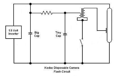
                      • Photo Flash Circuit

                        @lamare:

                        Here's the circuit diagram for the photo flash unit. Notice the similarity between this and the Water Sparkplug circuit.

                        Thanks for posting your results.
                        Attached Files

                        Comment


                        • Electrotek,
                          Got loaded question for you, Based on your experience. Do you know what the inductance of 110V coils sequential or parallel is? (I do believe that what Gray used in his motor.)
                          Mike

                          Comment


                          • Originally posted by mlurye View Post
                            Electrotek,
                            Got loaded question for you, Based on your experience. Do you know what the inductance of 110V coils sequential or parallel is? (I do believe that what Gray used in his motor.)
                            Based on my experience as a professional electrician, I don't use series or parallel inductances. This is something from electronics.

                            Mark Mckay recently posted a statement by a magnetics expert who said that coils in oppostiton have minimal inductance.

                            Comment


                            • I wanted to calculate approximate resonant frequency of grid, coils and cap used in Gray's motor.
                              Mike

                              Comment

                              Working...
                              X