
Originally posted by Ufopolitics
View Post
-
Thanks Bistander,Originally posted by bistander View Post
And I believe it would be even more interesting when I start analyzing Coils-Cores under different excitation signals...
perfectly aligned with this Equatorial Plane...or Parallel to it (simply put, in the same plane both)...agree on that?Originally posted by bistander View Post
I would post pictures later and maybe tomorrow a short video...but, based on the above facts, could you tell me first, off your thoughts, just as a guess...what would you think, the scanline deflections should look like when we align magnet that way?
Thanks and great test proposal from you!!
Regards
UfopoliticsLast edited by Ufopolitics; 02-21-2018, 11:55 PM.Leave a comment:
-
Backing up previous post by REAL Tested Images
Hello,
Here I will just BACK UP previous Post Claims with REAL TEST IMAGES, not just "painted" CAD's...
EAST VIEWS
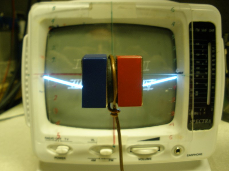
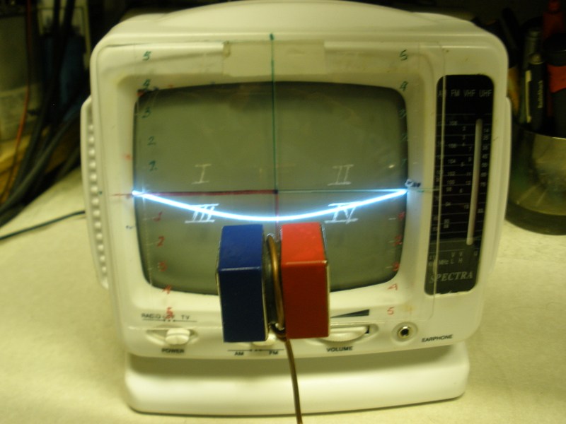
...
WEST VIEWS

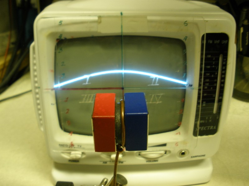
Interesting Notes: When I am pulsing a Cylindrical Coil as an "Exciter"...with a shorter -in length- Secondary, wrapped within same core, but "movable" along the common core axis...it results very interesting that the HIGHEST AMPERAGE LEVELS are ALWAYS reached right at the VERY CENTER AREA of the Exciting and much longer Coil/Core...curiously, coinciding where we can see a MUCH HIGHER "LUMP" towards either positive or Negative Zones on CRT Deflected Scanlines (remember pos-neg or "east-west" is just a relative surface concept)...
Regards
UfopoliticsLast edited by Ufopolitics; 02-21-2018, 12:35 AM.Leave a comment:
-
East-West CRT'S Scanlines...
Hello to All,
Basically on this post I will refer to the EAST and WEST CRT's SCANLINE Magnetic Field Views...
EAST VIEW:
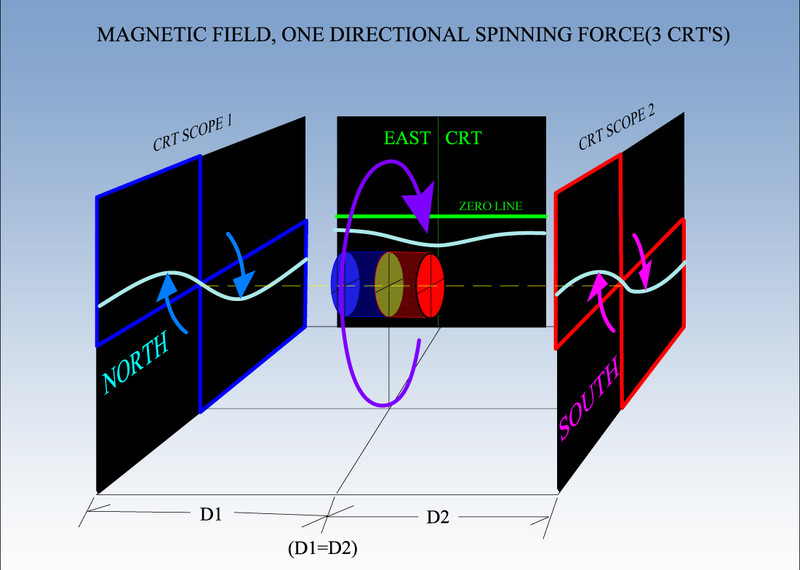
At the center of above Image we can see the EAST CRT and we observe a completely different Electron Beam Rastered Plane (2D SCANLINE) DEFLECTION.
The Green ZERO LINE used as reference on ALL CRT's, shows that whole deflection takes place on Both Negative Lower Quadrants, with a MUCH NEGATIVE DEFLECTION, EXACTLY at CENTER between both quadrants (Screen Center)...
WEST VIEW:ON A SEPARATE NOTE, LET'S REALIZE THAT THE SCREEN SCANLINE IS JUST "A TWO DIMENSIONAL (2D) PROJECTION" ON THE FLUORESCENT SCREEN FROM THE ELECTRON BEAM CONSTANT RASTERED (SCANNED) PLANE...WHICH TAKES PLACE IN THE THREE DIMENSIONS (3D).
Further on, I will be showing this E-Beam Plane deflections which develops in a 3D Environment within the CRT vacuum Glass Tube...just by making tube more transparent in a more advanced 3D Software CAD Program...
Besides the obvious fact that the 3D E-Beam swept, scanned, plane, also travels OUTSIDE OF CRT Screen...to meet ALL FIELD VORTEXES...
Regards to All
UfopoliticsLast edited by Ufopolitics; 02-20-2018, 11:06 PM.Leave a comment:
-
More Tests with Two and Three CRT's...
Hello,
Below are some pictures taken to a Permanent Magnetic Field REVEALING ITS DIRECTIONAL SPINS by CRT E-BEAM SCANLINES...:
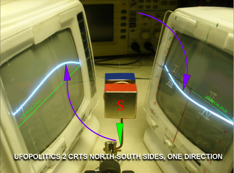
Above We are observing SOUTH Facing toward Screen, with TWO CRT's on each SIDE...can clearly see the deflections:
LEFT CRT= ABOVE (POSITIVE) ZEROLINE
RIGHT CRT= BELOW(NEGATIVE) ZEROLINE
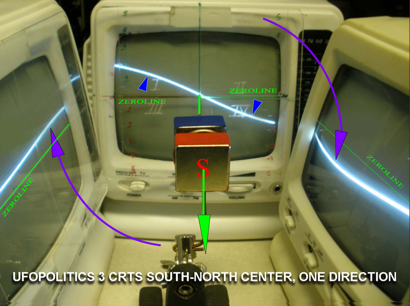
Above Image, same configuration, but now with a THIRD CRT in the BACKGROUND, Confirming the CLOCKWISE SPIN, according to FIELD POSITIONING.
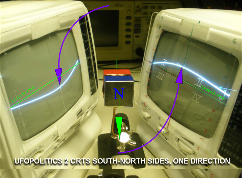
Meaning, now NORTH POLE is facing Screen, so we have:
LEFT CRT= BELOW(NEGATIVE) ZEROLINE
RIGHT CRT=ABOVE (POSITIVE) ZEROLINE
Completely opposite as previous setup...
...And below are the THREE CRT's CONFIGURATION...:
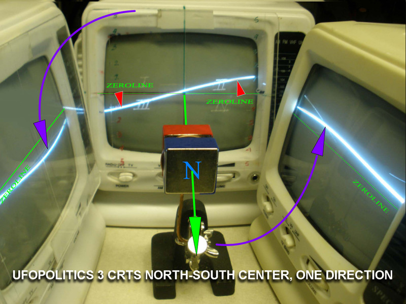
Where SOUTH POLE is facing CENTER-BACK CRT SCREEN, and we see the TYPICAL SOUTH SPIN on CRT's Screen...
Regards to All
UfopoliticsLeave a comment:
-
Real test verification...
Originally posted by Ufopolitics View Post
And NOW, ...IN AN ACTUAL TEST, with Two CRT's showing exactly SAME DIRECTIONAL SPIN as seen on previous CAD Diagram...:
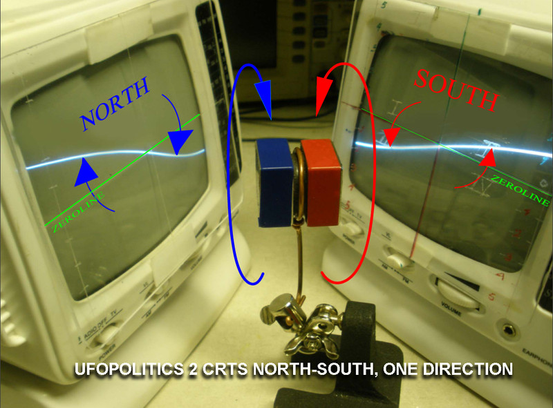
Therefore, this is NOT, just about Diagrams and CAD Images...BUT THE REAL DEAL.
Regards
UfopoliticsLeave a comment:
-
Opposite Spins=Same Rotational Direction in 3D Perspective View...
Even though, I have shown on my above quoted post, that a NORTH SPIN is COMPLETELY OF OPPOSITE NATURE to a SOUTH SPIN ...Originally posted by Ufopolitics View Post
When we get TWO of this CRT SCOPES, and set them according to below CAD DIAGRAM, meaning FACE TO FACE with the FIELD IN CENTER:
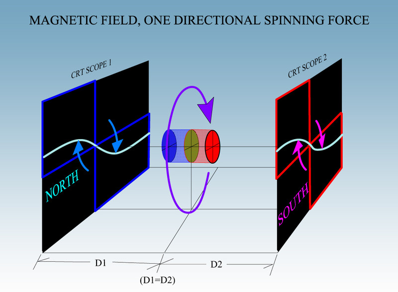
It is ONLY then, when we realize that BOTH SPINS AGREE ON SAME ROTATIONAL DIRECTION, from BOTH POLARIZATIONS...NORTH AND SOUTH.
Regards to All
UfopoliticsLeave a comment:
-
CRT Scope/E-Beam Scanline Identifying N+S Spins
Hello,
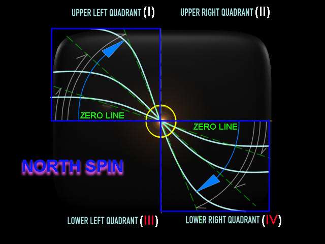
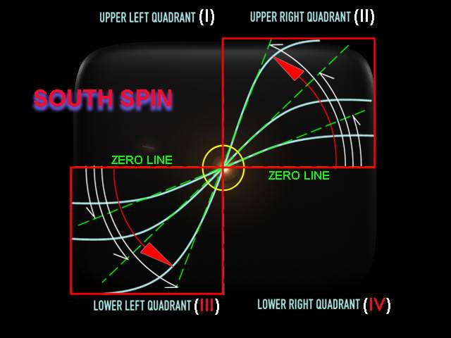
The First thing this Instrument will clearly REVEAL, and ALWAYS IDENTIFY SAME WAY, is the Opposite Spin Directions between a NORTH and a SOUTH Polarization (Poles):
NORTH SPIN SEEN ON CRT SCOPE
SOUTH SPIN SEEN ON THE SAME CRT SCOPE SCREEN
And this FAST AND ACCURATE RESPONSE works the same way for an ELECTROMAGNET which is being fed with direct DC Currents...Or whenever we pulse it with ANY SIGNAL we would be working with.
Example: If we just connect our Coil to a Regulated PSU, and start dialing UP Voltage and Amperage...we will see the ANGLES WILL INCREASE, tending to reach the Vertical Line at center of screen, and perpendicular to ZERO LINE.
UfopoliticsLast edited by Ufopolitics; 02-08-2018, 07:54 PM.Leave a comment:
-
Diy magnetic field scope/a scanline e-beam plane imaging tool.
COMPLETE MAGNETIC FIELD SPATIALLY AND THREE DIMENSIONAL TRUE GEOMETRY.
PLUS, realize Magnetic Field DO HAVE A Directional SPIN, and NOT like it was concluded by Hendrik Lorentz long ago...that Fields were not rotational.
Further on with Four of this small CRT units...and thanks to the HORIZONTAL SCANLINE ELECTRON BEAM RASTERING (SWEEPING) around whole Field...
It will help you ALL see (in my further CRT Video) that Fields are also SPATIALLY DIVERGENTONE SINGLE SPINNING FORCE, which includes its NORTH and SOUTH POLARIZATIONS.
Exactly as it has been stated by Ken Wheeler on his Free E-Book.
I have put together a short video below, where I have shown how easy it is to CONVERT any (working) Analog small and old B&W CRT TV...into this awesome tool.
[VIDEO]https://www.youtube.com/watch?v=E372P74Gq6k[/VIDEO]
DIY MAGNETIC FIELD SCOPE
If Anyone needs further assistance or deeper knowledge on how this small unit works...below is a MUCH DETAILED VIDEO where it is "dissected" all the way from each of the TWO MAIN DEFLECTING COILS to the electronic signals which generate the ELECTRONIC BEAM HORIZONTAL SCANLINE PLANE with all Full Color 3D Animated CAD's for easy understanding.
[VIDEO]https://www.youtube.com/watch?v=l7OzMURRU_k&t=1370s[/VIDEO]
CRT REVEALING MAGNETIC FIELD VORTEXES
This Tool is HIGHLY RESPONSIVE to Electromagnets which we are pulsing-switching, whether by AC, by Square DC Positive or Negative Pulses...or a constant Reversing DC Signal, generating an ALTERNATED DC Signal.
Regards to All
Ufopolitics

Leave a comment: