
ZFM Firing
I concur with Matt and Turion on the firing position just past the center of the coil. Various experiments over the past 6 months verify this over and over again. By the way it appears that the angle beyond the midpoint of the coil is about 20 degrees
Matt's explanation of the B field is dead on. Initially I was somewhat stumped as to why the magnet would blow right past the coil pole end that has the opposite polarity. Again repeated experiments verified this. The Neo magnets are definitely in surfing mode.
From the length of coil on time experiments (25 to 90 degrees) the greater duration dictates the amount of kick you obtain. The best results (speed and torque) obtained were in the 65 to 80 degree range of on time.
The air gap on the YZFM is about 0.375" at the closest approach with 1"Dx3/8"T Neo's on the current Iron rotor. The greatest speed was obtained 6 months ago with an Aluminum rotor with a slightly greater air gap and 3/4"Dx3/8"T Neo's at 36 volts.
My next move, one that is already in motion, is machining new Aluminum rotors. Simple design that is easily modified for differing Neo lengths and thicknesses. In this instance I am progressively tightening the air gap to 0.180" and later perhaps even more as the results dictate. Happy to share the rotor print. As a note the magnetic Iron bar stock is very expensive so Aluminum is useful for the prototyping mode.
Following James McD's lead I will test one rotor with a rectangular 1-1/2"Lx1"Wx1/2"T at this tighter gap. Expect to be on track with this end of the month or early next.
I will use the Loctite structural adhesive for the Neo's along with the Fiberglass shipping tape,
Thanks for all the sharing and information - just reinforces my initiative,
Yaro
-
Inconsistencies regarding Bedini video
Bedini notes that current drops to "zero" when iron core in introduced into the coil. He says the rotor speed increases while at the same time the current input declines. Usually when you introduce iron in a coil you increase losses in the system and you would expect the rotor speed to decrease. Therefore you have a system that appears to have an anomalous behavior. Two things to notice. First, the load is very light. The only load is the bearings for the rotor and air friction. Second, we don't know all the physical characteristics of the coil with and without the iron core. Usually you would expect the iron core in increase the inductance of a coil lower the resonant frequency. The physical characteristics are not obvious but there is the obvious increase in the rotational speed to the rotor. Therefore it appears the resonant frequency is actually INCREASING when the iron core is introduced. I was hoping to find more construction details to make this more evident. If these are available online, please post a link. Thanks in advance.Leave a comment:
-
Originally posted by Turion
All good input gentlemen, John Bedini did us all a favor by lighting
our way, that was his best under the circumstances.
Looking around i see machine materials. Tolerances could helped by
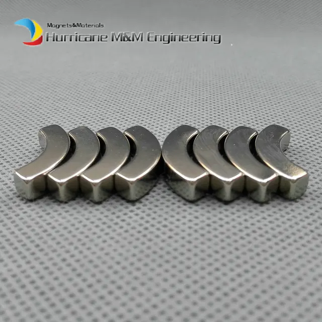
using curved rotor magnets. I'm thinking machining and prices.
DOUBLE ROTOR LOOKS GOOD, HEY?

https://www.apexmagnets.com/54mm-x-46mm-x-20mm-motor-magnets?fee=5&fep=168&gclid=CjwKCAjwpfzOBRA5EiwAU0 ccN1EhXNh6tX66kQ9hC5eENT9L-wjOmtCOnHFqijz_iD5UY_NVZwiJuxoCymoQAvD_BwE

 Last edited by BroMikey; 10-13-2017, 01:48 AM.
Leave a comment:
-
John was the one that told us that originally in the Bedini Monopole 2 group when he first showed that video of the motor with the iron pipe. Maybe 05, 06 time frame. Those groups have long since been shut down. But I remember it well because that was one of the few times I ever got straight answer out of him. He said there is no force exerted on the magnet, the magnet rides the flux lines on the side of the coil. He talked about the switching a little bit, switching direction at the center, then he never talked about the thing again until he started showing the printed models.Originally posted by Aaron View Post
MattLeave a comment:
-
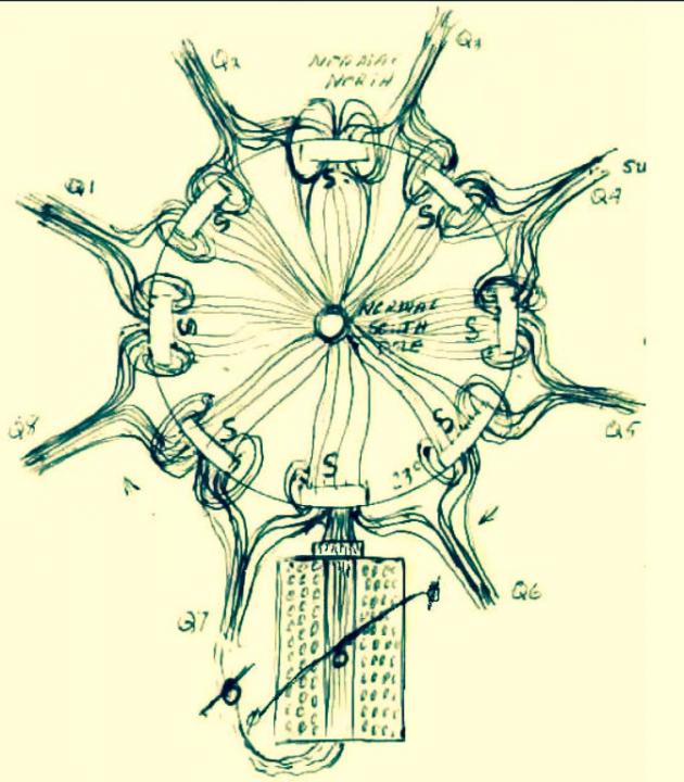
23 degrees
On an 8 magnet SG, you may have heard him always reference the 23 degree - you can see it written at the bottom of the wheel) - that is an analogy to the Earth's 23.5 degree tilt. And that is significant to the interaction of the "scalar" magnetic fields between the magnets and the coils magnetic field.Originally posted by BroMikey View Post
Leave a comment:
-
Good stuff Aaron I often wondered why John always drew his zeroOriginally posted by Aaron View Post
line crooked in the center of the magnet. I would look at that sometimes
and try to see if the line was allowing more room on the north or the
south and it did, then the next time it looked like there was more toward
the south magnet.
I just din't get that. I heard john say if it was day or night made a difference.Leave a comment:
-
origin of the motor
I believe Floyd Sweet wrote a paper on that topic. John was also not always consistent with his own definitions even though he knew what he meant. If you asked him about the zero force reference, he would point to the center of a magnet. And the Earth's degree of tilt relative to the sun was important to him and is why in the ZFM diagrams and other coil diagrams he always draws that diagonal line through the Bloch Wall.Originally posted by Matthew Jones View Post
For anyone interested, this is where I tried to get some discussion going about John's magnetic model since I have all his old lab notes on the subject that were never released. John Bedini's Magnetic Model They'll all be published in due time.
The origin of this Neutral Line motor was around the same time as his Space Flux Motor (the one in the glass case) and appears to be all pre-Ron Cole time.Leave a comment:
-
Although there was a whole paper on the subject of the entirety of the b field of a magnet and the force that is included, I cannot find it. This question and answer cover the naming of this motor as a zero force motor.
Question
AnswerIt doesn't makes sense to me that when charge is moving parallel to magnetic field, force on charge by magnetic field is zero I have done some research and can't find proper answer some people say that answer lies in Lorentz transformations and special relativity so why isn't charge experiencing force?"Resulting forces is the key word"A B-field exerts force on a moving charge, in a direction perpendicular to the B field. If the B field and the velocity of the charge are in the same direction, then there is no way to distinguish any single direction of the resulting force (there's a 360 degree spread of perpendicular directions). So, the only force vector that has no direction must be the correct answer (i.e. zero force).
A B-field exerts force on a moving charge, in a direction perpendicular to the motion of the charge. By similar reasonong to above, this also means the force must be zero when B and the velocity of the charge are parallel.
If you close 4 electromagnetic coils into a loop or a gapped loop all force exerted from the poles is neutralized. Since the poles cancel each other there is no Lorentz force exerted. IE "Zero Force" Lorentz force being the force calculated when push or pull occurs in a magnetic Pole.
Just because Lorentz force is canceled does not mean that all flux from the coil is neutralized. When the permanent magnet of the motor is perpendicular the wire in the coil 50% of it flux is opposed to the flux generated in the wire and the B Feild. This is the portion of the permanent magnet that drives the zero force motor.
Howard Johnson extensively researched this reaction in permanent magnets for continues rotary motion.
MattLeave a comment:
-
yes very good post keeps my mind on the subject matter. I have beenOriginally posted by Turion
thinking about where i am going in terms of tolerance. Here is a quote
on electric motor air gaps. .010" is a standard
The air gap Lg (Fig. 5.100) should be chosen to give the greatest torque per stroke. This approach will, however, tend to make the air gap length small. T. J. E. Miller (1993) recommends that it be about 0.05 percent of the rotor diameter. This tends to produce air gaps in the 0.007- to 0.010-in range for small motors. This can lead to manufacturing problems and increased costs in commercial-type motors because tight tolerances will be required on many parts. Holding a 0.010-in air gap is very feasible in most manufacturing situations and is a good initial selection. Small air gaps increase torque but also increase audible noise.
Leave a comment:
-
Just words
Hi Aaron,Originally posted by Aaron View Post
How do I know what you mean by indisputable without researching you, looking at your entire body of work and seeing it from your perspective instead of my own, which is logically derived from creditable definitions and worldwide body of literature, language and general understanding? Felix Bloch was a distinguished scientist who won a Nobel Prize, had a lecture hall named after him at Stanford and was the first director of CERN. Using his name for whatever reasons Mr. Bedini had is quite different than redefining COP. It is disrespectful IMO.
But let's discontinue this sidetrack. Thankyou for your responses. I'll try to not let established word definitions influence my opinions of John Bedini's work.
Regards,
biLeave a comment:
-
Jame's Zero Force Motor
Originally posted by BroMikey View Post
Hi All --
The easiest way to keep the RPM's down is to keep the voltage input to
the Bedini-Cole circuit under 36 volts. Since everyone will build their Zero Force Motor slightly different the resonance point where your motor coil goes into a 2500 RPM jump in just a few seconds is the scary part. Depending on the reed switch timing I can make my Zero Force Motor do this at 40 volts or at 55 volts. I have pushed the voltage up to 66 volts but only for a few seconds before backing the voltage off. I have had two events where the magnets few off even though they were glued on with some strong epoxy. To get to the higher voltages without using batteries I made a power supply that will go up to 180 volts DC with an adjustable AC input. My Zero Force Motor will start to spin at 2.7 volts. Currently I am working on a special Pulse Width Modulator board to control the speed of the motor. I am looking into buying some shaft to shaft hook up pieces to hook my Zero Force Motor up to a Volkswagen Alternator. Take a look at my YouTube Channel for my videos.
https://www.youtube.com/watch?v=uiMZZ0_0X10
https://www.youtube.com/watch?v=mRfm5lFc3TI
https://www.youtube.com/watch?v=utjk-PT7mFo
-- JamesLast edited by James McDonald; 10-14-2017, 08:00 AM.Leave a comment:
-
Okay Okay I got it.Originally posted by Turion Not bad, that sums it up nice and
easy for guys like me to understand the "WHY" ya know not just another
mtr but one with those characteristics should be an advancement.
When I run my SUUL coils the motor needs to go fast. Can one of these
run at normal speeds say 3000-6000rpm's? Or does it need to go over
10,000 rpm's or like Yaro said his runs 13,000? Can they be slowed down
some from 13 grand and still get the energy effect?
In other words does each zero motor build have to reach a specific node
(or as it is called Sweet spot ) to be effective?
What if I wanted to run half that speed? That would still be double
the r's of what I got now. The thing is I don't know if I can get the
money for all that machine work for high tolerances.Last edited by BroMikey; 10-11-2017, 08:36 AM.Leave a comment:
-
John Bedini's model
The Bloch Wall is giving a reference to a specific location on a magnet between the poles - that is what it is called by definition. That definition includes an OPINION of what it is and how it operates - nothing more and nothing less like countless other definitions in physics, astronomy, agriculture, etc... that for the purposes of identification, we know what they are regardless of the fact that many of the definitions to define such things are completely WRONG. It is only called a Bloch Wall because of someone's name and in the mind of the conventional viewpoint, that person must automatically know more about the intrinsic nature of it, which is never the rule - in reality.Originally posted by bistander View Post
Whether it is what the conventional viewpoint is or not is one issue and a completely other issue is how John Bedini sees that Bloch Wall operating. No matter what, we know that we are talking about the place on the magnet between the poles and that is indisputable. What is also indisputable is that John Bedini has his own viewpoints, right or wrong, about what is happening at that Bloch Wall, period.
Based on John's viewpoints of what happens there is at the premise of many of his magnetic models and that is also indisputable. Whether he is right or wrong is one issue and is completely separate and irrelevant from the issue of what his viewpoint is.
Now that we know what his viewpoint is, in whole or in part, the Zero Force Motor is a reference to a motor that has a significant if not the most significant relationship with the Bloch Wall of the coils surrounding the rotor and this is also indisputable.
Yes, words have meaning and for good reason but when a word identifies something that is supposed to have a certain meaning based on how it is perceived to operate and we come to a better understanding, then we clarify that definition by upgrading it which John did quite well in brief in the video that Bodkins posted. Noone is required to agree with that understanding.
The same issue exists with the definition of COP or coefficient of performance. I can't tell you how many engineers have tried to argue over the years that it can only apply to heat pumps even though the fact is that it is a ratio between output work compared to what we provide excluding free environmental input - that does not mean we need to create a completely different word (or phrase) for mechanical systems that create more work than we have to input, it doesn't include electrical systems that create more work than we input, it doesn't include chemical systems that create more work than the sum of the input chemicals on their own, etc. We can still use the term COP because it is a reference to a concept or a thing, etc... and we understand that. Therefore, we can expand the definition to go beyond heat systems and can use COP to explain the performance of all systems that produce more work that we have to input.
This is the same thing as Bloch Wall - we know it is that place where the polarities separate so John uses that definition because it is common sense about what he is talking about is a place on a magnet then he goes on to explain how he thinks it operates - very simple.
It shouldn't be called a Bedini Wall because he didn't discover a new place on a magnet, just a way that an already known place on a magnet may actually operate, which is different than originally thought.
You can't define an elephant by grabbing it's tail or its leg, which is analogous to looking at John call this motor the Zero Force Motor, Zero Vector Motor, etc... you have to look at his work holistically and take the entire thing into account as one whole system. Otherwise, you're defining an elephant by only grabbing its leg.
So again, research it, look at John's whole model and see it from his own perspective instead of your own.Leave a comment:


Leave a comment: