
I have built lots of things that work. What you have with this little system I tried to share YEARS ago (and it took you ten years to figure out how to build) is toys in a sand box. I don’t have one running because I am WAY beyond this and don’t have room in my shop for toys.I don’t need to take a step BACKWARDS. LOL.
Yes I will help Wantomake, and maybe some others. But I am definitely done helping YOU. What you built only worked by accident because we BOTH know you didn’t build it according to directions. It just so happens that it works that way too.
Sometimes luck is more important than skill. I have had more than my share. Both good AND bad.
-
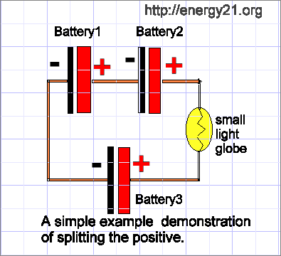
Here we still need a pump like John Bedini talked about when he built his tesla switch. This picture is from many galaxies away, back before the dawn of the internet when men roamed the earth. You were still in diapers.
We need to add a pump John said but this is the basic free energy design or battery layout.
John would say "don't change it" try it first then change it.
 Last edited by BroMikey; 08-02-2022, 10:39 PM.
Leave a comment:
-
No I didn't wait long and so I should lose ions in the deal but will it go dead? We will see.
7th run startup numbers. Maybe Dave stayed up all night again wondering how mine works.
At ICE STUFF you can see the simple circuit diagram by John Bedini showing 3 penlight batteries arranged for 3 battery operation. I'll show you later but John always added that you need an energy pump in the system. The SSG was a great pump and is a boost converter.
So far in the picture I've gotten 27WH out of those dinky battery packs and still showing some charge
 Last edited by BroMikey; 08-02-2022, 10:37 PM.
Leave a comment:
-
dude that is so awesome. Nice Li ion battery. I wonder if you ever used them?Originally posted by wantomake View Post
Here is my 3rd day run. I slept like a rock. Dave is okay he will help you wanto in secret. Him and Bob will be a secret also. Same ole. Hang in there. Can you see the light now Dave?

 Last edited by BroMikey; 08-02-2022, 09:26 PM.
Leave a comment:
-
This is the lithium setup I'm reassembling to use as a 12volt battery for experiments. It's a 3s 8p for each 12 volt segment. Notice the top of the "brick" where I started spot welding the tin connecters to the batteries. 3 in series with 8 in parallel. The next to bottom picture is what these batteries were with a BMS on each segment or group of 3s 8p to make the 12 volts. But I took them apart to make the 24 volt stacks in picture below with the UPS pictured to the right. Each stack has 7s 10p or 70 batteries that charge up to 29 volts +-. A 60 amp BMS is installed in each stack. The above brick has five 3s 8p 12volt with 5 groups and I'll leave the BMS off if I hear it from you guys it's ok to do so.
IMG_5875.jpg
I am waiting to finish this setup or brick but waiting as I charge my spot welder which is a hand held type not a bench type. Yes I should've waited and kept at lest one brick assembled but you know.Last edited by wantomake; 08-02-2022, 06:43 PM.Leave a comment:
-
wrong answer againOriginally posted by BroMikey View Post batman! at least you are consistent.
Leave a comment:
-
ding ding ding winner!Originally posted by Turion View PostLeave a comment:
-
Turion,Originally posted by Turion View Post
I really want to see how Bob French is using lithium batteries. If he's using the batteries straight connected or uses a BMS. I see BroMikey has his straight connected and getting results.
I've about 400+ lithium 18650 batteries. I've assembled 280 so far for solar backup. Just a start. But have a couple hundred left over that I could use as needed. I use the lead acid batteries only for these experiments.
I'm in need of shop time to answer some of these questions.Leave a comment:
-
That is all I ever get, don't forget your ball and bat. You been saying that for years, gonna quit, uncle and so forth.Originally posted by Turion View Post
dont take out your inability to succeed on us. Now suddenly bobs got a winner? Bob has a zero force motor. Yeah.
I guess you must be embarrassedLast edited by BroMikey; 08-02-2022, 09:22 AM.Leave a comment:
-
You got exactly what you deserve. And there won't be any more help from me. I can promise you that. I'm done.Leave a comment:
-
I talked to Bob French today and he put together a setup using a boost and 3 lithium iron phosphate batteries. He has a load running between the + out of the boost and the charge battery. He ALSO has a load across battery 3. In the old days I talked a LOT about balancing the load across battery 3 with the load between the positives, and Bob has managed to do that. He's old school 3 BGS like me. I believe he has a 10 watt load on the output of the boost, and not sure what the load is on battery 3. The system has remained balanced for about four hours now, where the primaries don't go down and battery 3 is at almost a full charge, but doesn't go up. The system just puts out energy, running both the loads, while the voltages in the batteries hold steady. He is going to run it all night and see what happens. He is also going to shoot a video where he walks through his setup. His load on battery 3 is one of those LED light strips you roll out under cars to light them up while working on them.
This seems to be MUCH easier than doing it with Lead Acid Batteries. Balancing a load could take me a whole DAY, and by that time my batteries were discharged and I had to recharge and start over.Leave a comment:

Leave a comment: