
As we all know Mack has stated that fork tine terminations are
not revealed by him due to his more advanced work being patented by
another group. What if there were another material in the gap between
tine and stator magnet that constitutes terminate? I don't know, but at
the same time as we seek out the shielding benefits, I wanted to suggest
termination using the right shape or material might enhance what we are
desiring. A one way pull just like we have now but with 0 kick back.
It is just speculation on my part. Eddy currents are a powerful force.
[VIDEO]https://www.youtube.com/watch?v=Baq4whkHCIk[/VIDEO]
-
Listen to this guy talk about shielding on a neo magnet N52
1" X 2" X 1/4" The goal is to create a one way force. He uses tin,
plastic spacers and dead carbon battery to space also.
It is not like our motor but he is the only one on youtube that
goes into great detail.
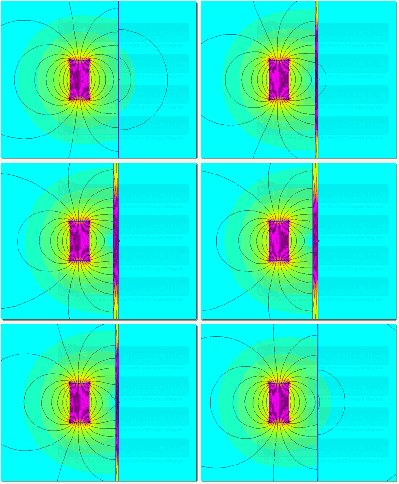
What if we could make the sticky spot 0 through shielding?
This is what he points out, that there is a sticky spot and
then he shows you his shielding solution. In our case we have
cancelled out much of the sticky spot and at the same time
are using the forks to redirect flux without moving parts. Now we
have been directed to further reduce any reverse pull, and shielding
maybe one answer.
[VIDEO]https://www.youtube.com/watch?v=KhY7hHb2l6o[/VIDEO]Last edited by BroMikey; 10-11-2015, 06:12 AM.Leave a comment:
-
hey ShyloOriginally posted by shylo View Post
You were right in that a small kickback was there, I stand corrected.
However Mack did say that we are at the turning point and that even like
it is, the motor will run with 6 - 8 stations for ramps and magnets.
I have also been thinking about 8 stator magnets and ramps verses just adding
rotor magnets. And I think we need all of the ramps to make it go.Last edited by BroMikey; 10-11-2015, 01:01 AM.Leave a comment:
-
Hi Mack,
That's good info ,understand that it is important.
Thanks artvLeave a comment:
-
Luke, Feel the force!
Uh, I mean spread the force vectors. Spread the tines at the end. Couldn't help myself.
RandyLeave a comment:
-
The blunt end of the top ramp. If the ramp is good up to that point then what if from that point on, the vector force between the ramp tines and rotor magnet remained at 0 while rotation continued and the attraction between the tines and rotor could also be reduced to 0?
Regards,
MackLast edited by MadMack; 10-10-2015, 09:53 PM.Leave a comment:
-
Hi Friends,
I also think that the ramps need to be shorter and more sharp at the stator, otherwise the tuning process of rotor and stator magnets to pass without of only a little drag would not make sense.
Best regards
SiggiLeave a comment:
-
Originally posted by MadMack View Post
Hi guys
What I think Mack is saying is that surface area/mass of the fork tips
and exposure area are all part of tuning. Mack says that UFO's video
has a kick back at 2:46 like Shylo was talkin
Look at the ramps. And think think think.....

Leave a comment:
-
Too much beef!
Mack,
What i get from that video in slo-mo is there is too much metal at the end and the ramp extends too far beyond the stator magnets.
Also, watching this brought to mind an image of my rotor passing the balanced magnets with no ramp. There is an acceleration, then deceleration that takes place as the magnets pass each other. It has got me thinking about the accelerations side and the ramps. I wonder if we can use the ramp ends to extend that acceleration of the rotor as it approaches the stators.
Thanks Mike.
Cheers,
RandyLeave a comment:
-
Ufo,
I never wrote it because I never got a 2 pole like this one to actually motor. Logically, you would think that it would, but that was not my experience. I am not an expert on magnetics by any stretch of the imagination and I can only explain how this works in layman's terms. The back pull from a ramp has to be eliminated or dissipated as much as possible. The rotor acceleration has to extend to the point where the next ramp can start to take hold of the rotor magnet before any remaining back pull from the previous ramp can exert itself. Watch the video again about 1:07. You can see the acceleration out to about 210 clockwise degrees from vertical, then there is a tug that slows the rotor back down. It's not enough to stop the rotor but it does slow it down. Ufo, I do not want to discourage you but the two ramps in the video need more work. I hinted at that in my last post. The bottom one is OK but could be just a little better. The opposite ramps are not identical in my motors, in case that helps.
This motor is similar to an internal combustion engine in this sense; the power produced is a sum of the power pulses in time. The more pulses per second, the higher the rate of power produced. It's the same with a gas engine, more HP as the rpm increases.
Tachyoncatcher,
I can't come right out and say where the ramps terminate. Sorry, that's a gray area I have to avoid. Study my reply to Ufo above. Otherwise, you got the idea. Remember the vectors at all times.
BroMikey,
At 2:46 you can see the rotor magnet experience a strong back pull right past the end of the top ramp.
Regards,
MackLeave a comment:
-
What candle video?Originally posted by tachyoncatcher
@Mack
at 2:46 minute it shows the rotor magnet slowing and just how little
kick force is present with all of that power available in magnets.Leave a comment:
-
Geometry
Originally posted by MadMack View Post So, if one was to terminate the ramp to a point. Say, ending at the middle of stator magnet. The ramps "hold" on the rotor magnet would be diminished by geometry, even though the magnetic induction force is the same, as in the nail example. It's all in the geometry. Big heavy induction at the beginning, with gradual release using two forces. Decreasing distance between ramp and stator which maintains the pulling force past mass center, and shrinking mass through geometry which minimizes the release forces.
My next test,
RandyLeave a comment:
-
About a simple question...
Hello to all,
There are two comments from two different members building here and I am citing them both below...
Originally posted by tachyoncatcher View PostI would like to know where in this Thread do Mack writes that just Two Stators with their respective Ramps...and the rotor with All Magnets properly set and aligned ...This configuration is supposed to deliver a continuous rotation?Originally posted by Turion View PostLast edited by Ufopolitics; 10-10-2015, 06:51 PM.Leave a comment:
-
A simple experiment.
Secure one of your neos to something. Take a nail and holding it by both ends touch the pole of the magnet with the nail crosswise to the magnet. Feel the amount of force it takes to pull the nail off.
Take the nail and touch the magnet crosswise with the pointed tip of the nail over the center of the face so the nail contacts only half of the magnet pole. Compare the amount of force it takes to pull it away. It's noticeably less.
Now take the nail and place the point of the nail in the center of the magnet pole, but this time hold the nail vertical to the magnet like you are going to hammer it in. It takes a lot less force to remove the nail.
In Ufo's video, look at 2:46, as the rotor magnet passes the stator at the top.
Last edited by MadMack; 10-10-2015, 05:55 PM.Leave a comment:


Leave a comment: