
I sent in the private space of each one of the link by my last video, but is not interested, so i will make the public, having to comment on another forum. Who will be affected? I'm not
That is the link https://www.youtube.com/watch?v=fNOhuYaU1WI
-
@UFO
You missed what I was saying to you.
This video and the first video rotor angles are opposite. Did you hear
me that time? That is what it clearly shows in the video's you made.
I went back and looks several times. Just do a quick visual and you will
see that you first video has the 30 degree angle rotor field pointed away
from the ramp, while your new video has the 30 degree angle on the rotor
magnet pointed toward the induction ramp.
Opposite. That is what I see.
Back to the shop
I'll show you what I mean later. Last edited by BroMikey; 10-21-2015, 07:00 PM.
Leave a comment:
-
In the private of each member of this team will be the last video uploaded by me.
Good luckLeave a comment:
-
however, for both cases the rotation is exactly the same.
Mack's previous Post:(<<<LINK TO ORIGINAL POST)
Now, below are both diagrams together, next to each others, Mack's and mine...for easier comparison:Originally posted by MadMack View Post
[IMG]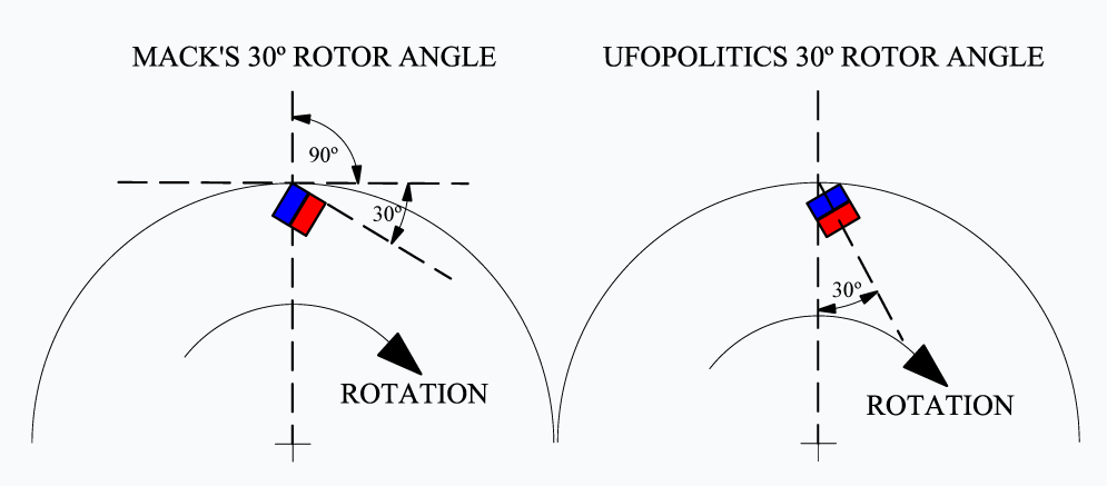 [/IMG]
ROTATION IS EXACTLY THE SAME FOR BOTH CASES.Related to smooth versus coarser iron surfaces and "passing by" magnetic fields...I believe this issue must be analyzed from almost a microscopic way, where coarser surfaces have heavy grindings with deeper grooves where the field "sinks in", plus each deep streak reflects different and random angles to the field which is PERFECTLY DIRECTIONAL.
A smooth, basically even and aligned surface would be offering lesser resistance to the field rotation.
This is only my opinion...so, don't take it for "granted" until you experiment and see it for yourselves...
Well, getting back to work...got to add another module with ramps probably today.
Regards to all
UfopoliticsLast edited by Ufopolitics; 10-21-2015, 01:11 PM.Leave a comment:
-
I decided to go into the lab for a few more tests because after
realizing I was going the right way from the beginning maybe I
am now going in reverse. Oh well Mack did say it goes into reverse.
Here is what happened. I had been going one direction for 2 weeks and
then I just recently changed direction. So I have given ample time to
both directions as far as ramping goes.
BUT I had never before set out to try both directions one after the
other with all of my ramps, with or without a stator.
This is my conclusion.
The field angle pointed at the ramp in the distance as it comes around
picks up the field much more powerfully. Once the rotor magnets get
over their stator magnets the force is cancelled leaving very little
kickback at the ramps end. So momentum from ramping over comes
what little cancellation kickback is leftover and the magnet continues
on it's way. We all know that.
The important thing is that when the fields are pointed toward the induction
ramp as it comes around, field strength is greater so the rotor magnet will
start it's run much sooner, almost twice as far away will it pick up the
ramp when using a stator magnet.
You see before when I did these tests I did use a stator so the difference
was only slightly noticeable, but upon re-investigation I must say that the
fields need to be pointed toward the ramp for best results.
It gets confusing with so many ramps and the way the ramp is angled
so I think this all takes time.
This really made a lot of sense to me after my last video where I showed
how the opposite side of the rotor magnet was sometimes interfering on
the repulsion side and now those anomalies are all gone.
So for me it is back to may original direction when Mack stopped me before
and asked me if I was really sure of that direction. So seeing how there
are only two directions I changed it.
So now I have tried it the other way for awhile. Last edited by BroMikey; 10-21-2015, 09:03 AM.
Leave a comment:
-
Okay Here it is GUYS @ UFO
@ UFO
I made these two pictures so we can look at them to see which
direction makes the most sense. I am stumped now.
Which way does he go?

Leave a comment:
-
Thanks UFO on the comment above, I didn't know.Originally posted by Ufopolitics View Post
Mack will be here soon enough to set the record straight on your nice
set up. You really are a good man for this job. I am not for sure on this
but I think your new rotor is backwards? I am getting mixed up. You see
the reason I say that, is because the last video was better than this one.
I see your beautiful new plastic, it is so nice and the forks are the same
but the rotor magnet has been changed so that now the 30 degrees is, I
think, the wrong way? It worked way better before.
And Mack did say it was right on the first video.
The way we get to a 30 degree angle is irrelevant. Excuse Me.
Just havin a bit of UFO, don't mind me. I am here to help so that's the
way it is going to be. I hope.
I don't know, maybe flip the rotor over? I am trying to think.
Just put the old one back on.
You see this is like the way I was doing it before and I thought we had
agreed that I was going the wrong way? I think I was going the wrong
way because now it seems to work better where the leading edge being
closet to the stator .
It is good to try it both ways. You will see that this way is backwards.
These are my thoughts and like I said Mack will be here soon enough.
One more thing. I tried what you tried on the attraction side by spreading
out the forks? Yeah and it made my rotor magnet stick.
Nice work. I am going to try it again and let you know. Try it the other way.
There is always a 30 and 60 degree angle on either side depending.
I'll check it again to see if it makes more sense in the long run concerning
the way the rotor magnet faces a ramp from a distance.
You have me thinking again. But one thing I can tell you beyond a shadow
of a doubt, your other rotor kicked out a magnet on the repulsion side
like it should be. This experiment proves it. So now you know.
 Last edited by BroMikey; 10-31-2015, 07:05 AM.
Leave a comment:
-
Testing different Ramp set up...
Hello Guys,
[VIDEO]https://www.youtube.com/watch?v=I_w8qgtCCjw&feature=youtu.be[/VIDEO]
TESTING RAMPS IIIPage 15, Post 442
And not like I had it in previews build on videos as well in all my previous CAD's
Big difference there, much easier to adjust center line and mounting not so complicated (thanks Mack!)...so I had to re-adjust almost everything...and ended up remaking a new rotor...a new base and stand...plus the rest...
Now, this small, 1/4 " cube magnets...are a piece of crap...N-52, N-42's from K&J Magnetics... it is about their very weak pulling force which is actually much less than what they list them for. They only Max pull in class 1 (steel/magnet) not even 3 lbs. And on top of that they have terrible differences between all...far from finding a pair that is close enough...
I bet on bigger magnets the differences would be much less, and small errors in parameters...plus the huge pulling force of 21 lbs...
However...I am going to get this Motor running even if it moves like a Clock...on low batteries...
Last edited by Ufopolitics; 10-20-2015, 09:36 PM.Leave a comment:
-
Same Here
Ditto here Mack. I'm not even close to discouragement. Actually quite excited. !
!
RandyLeave a comment:
-
Still in
Hi All,
Just to let you know, that I am also still in. I have my basic setup done and am testing first ramps on repulsion side. I already get a good throwout acceleartion with one ramp (3mm thickness)but major problems with drag during entering phase. Good ramps are not that easy to build and cut. My CNC is not made for milling steel. I use 12x12mm cubes N48 magnets on a diameter of 300mm for the rotor. The stator is just two of them. Distance of rotor to stator magnet is approximately 10mm. The first step is done and works perfect with my setup, exactly like described by Mack. Unfortunately I do not have enough time to work constantly...so also only step by step It would be brilliant if we could work out a kind of To Do list or Check List for the ramps to improve them faster, means what to do, if the rotor behaves like this or that for repulsion side and attraction side.
Thanks Mack for everything you have given us until now. We have just begun and will end when this beast is running.
Best regards
SiggiLeave a comment:
-
Still experimenting
Not to be a yes man but I agree Ufo.
I have the 1/2" N-52 mags, same size 12" rotor made from same material as yours Madmack.
The exact fabrication of ramps has slowed me but opened understanding of how it works. No excuses, no useless comments.
wantomakeLeave a comment:
-
It is absolutely Not your fault...at all.
Originally posted by MadMack View Post
Mack,
It is absolutely NOT Your fault that WE, all replicators on this Thread,(and any other around) have NOT come up as of now with EXACTLY the same spec set up as you have described in your first, second and third posts.
So far I have NOT seen ONE SINGLE identical replication based on your description...
I, include Myself, of course, within that group of members here that are NOT doing the supposed work.
Assuming that it "should" work with "similar" components...IS NOT the EXACT WAY.
I assumed that 1/4 cubes as long as they would be of N-52 would work...however, the pulling force from this magnets does NOT work the same way -in scale- as the geometry does.
It is NOT the same a magnet that can pull 20 pounds as one that can ONLY pulls 3.0 pounds...
You have rendered here a motor that has work for you with certain spec's...but the actual relationship based on required pulling force to be either scaled up or down has not been established as of now...and maybe you don't even know it yourself, just because if something WORKS for you a certain way...THEN, WHY IN THIS WORLD SHOULD WE CHANGE IT BEFORE MAKING WHAT WORKS TO PERFORM ??!!
I believe You should just IGNORE all comments from the stupid People...unfortunately this world is FULL OF THEM...a MAIN REASON WHY...we are ALL still dependent of OIL, GAS and Diesel Farting Machines!!
Until someone comes up with the IDENTICAL setup you have described here...and claims it don't work...ONLY THEN...We should pay attention to...BUT no comments Till WE ALL SEE IT ON A VIDEO...Period.
Otherwise is just PURE BS.
Kind Regards
UfopoliticsLeave a comment:
-
Mack,
Not discouraged at all, just not used to metal working (ramps) so moving slow at that stage. Thank you for staying active here.
KentLeave a comment:


Leave a comment: