
The clip lead for Xee2 or Stiffler functions as a counterpoise.
Some claim it is like one plate of a capacitor other say it is a capacitive coupling.
It was developed for ground systems to overcome low resistance
in soil for monopole antennas. later more suffisticated arrangements were developed.
This explanation is not entirely complete. In the Stiffler one wire experiments I got better results less build up time
by making a heavier gauge clip lead. It is my understanding that Tesla would terminate some single wires with rounded ends
sometimes spheres this is in contrast to sharp pointed ends.
These methods can help distribute where and how this may support
part of the system by reflecting the wave seen as an artificial ground.
Some interesting phenomena have been reported
under the subheading Cautions Using Counterpoises:
Counterpoise Systems
Not all grounding systems are under ground and others have tiers of radials below ground
shown in figure 5 which are commonly found with Marconi antennas.
-
As Level has pointed out, this is perfectly normal behavior for a high frequency AC circuit. To get a better understanding of what is going on look up "standing wave ratio" or SWR on the internet or in the ARRL amateur radio operator's handbook.
CarrollLeave a comment:
-
Hello Bob. I don't think the capacitance of the wire to the circuit really has much at all to do with it. I would think you can move that wire further away from the joule thief signal generator and it will work about the same. AC is not DC, and it is perfectly normal for AC in the range of even low KHz and on up in frequency to be able to pass energy down a single wire. This concept is used all the time in radio. You can connect a single wire or whip antenna to a radio receiver or transmitter and the radio signal is able to pass down the single wire to the receiver, or able to go from the transmitter down the single wire, and act as a transmitting antenna to radiate EM energy from the antenna. The joule thief circuit is acting as a signal generator sending an AC (actualy it is probably pulsating DC, but it amounts to the same thing) 'signal' (waveform) down a single wire to an AV plug, which converts the AC coming down the single wire to DC. The LED is then being lit from the DC. Again AC energy passing down a single wire is perfectly normal for AC. You do not need a return wire for single wire power transmission, although having both the 'transmitter' and 'receiver' grounded can improve performanace at lower frequencies. At higher and higher frequencies the capacitive reactance from the circuit to the ground becomes less and less, but there may be other factors involved due to frequency itself.Originally posted by Bob Smith View PostLast edited by level; 05-26-2015, 04:23 PM.Leave a comment:
-
Hi ErnstOriginally posted by Ernst View Post
Thanks for the post. Interesting HF-HV effects. I have a few questions:
Is your 2.5pF capacitance actually a capacitor or a wire with this same capacitance?
Does your capacitor then constitute a kind of extension of the open leg of the bulb (like an antenna)?
BobLeave a comment:
-
Here is a slayer exciter coil that outputs 10 KV at 374 KHz. Its topload is connected to one wire of a light bulb, the other wire of which is connected to a small capacitance.
To charge the capacitance to 10KV takes 0.117 mJ.
At 374 KHz this energy is supplied and removed 374000 times per second, so the connecting wire transfers this energy 748000 times per second. That is roughly 8.75 Watt.
Enough to make the 25W bulb light up a bit.

Ernst.Attached FilesLeave a comment:
-
-
Single Wire Setup Inspired by Doc Stiffler
Here's a blog entry by an EE inspired by Doc Stiffler's SEC device.

He uses a signal generator in his first proof of concept example.
His second (Ultra Wide Band) example uses an MPSA06 and a variable inductor:
[IMG]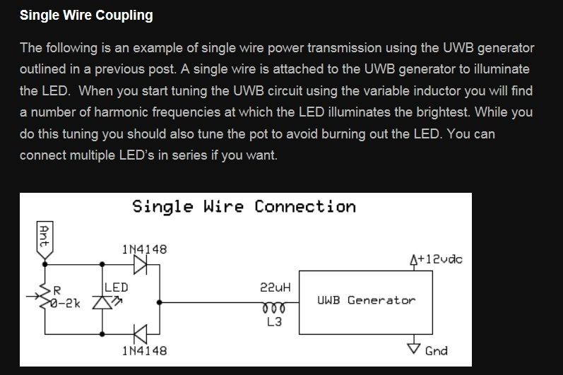 [/IMG]
[IMG]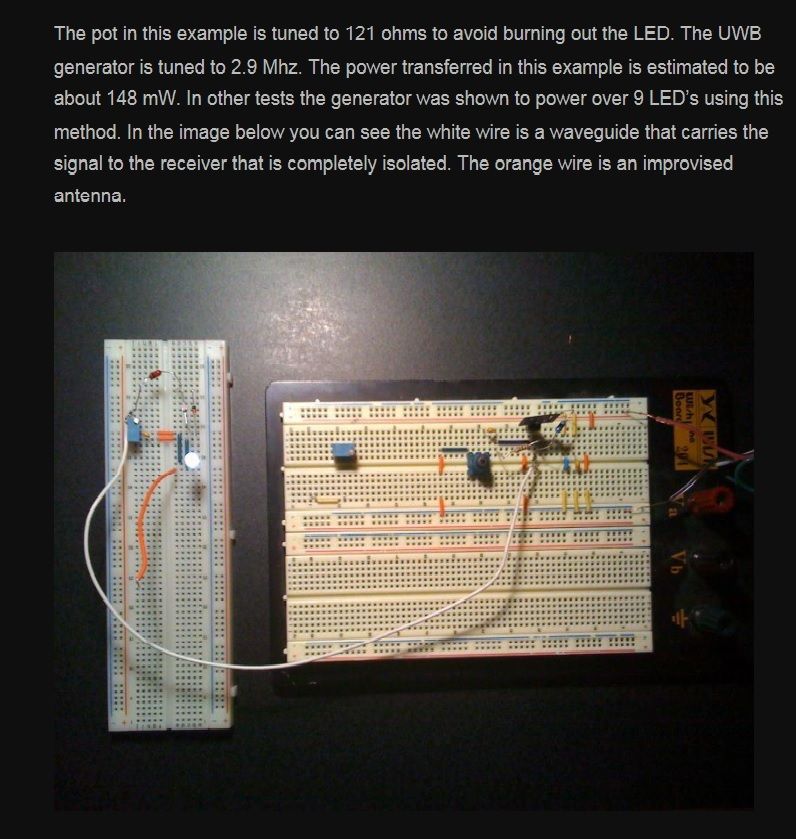 [/IMG]
In both cases, he uses two hi-speed schottky 1N4148 diodes in AV plug configuration. Without this diode configuration, he claims the setup won't work.
The antenna also figures into this setup. It seems to be a common element in single wire power configurations.
Some of his observations about the nature of the circuit and what's happening:
[IMG]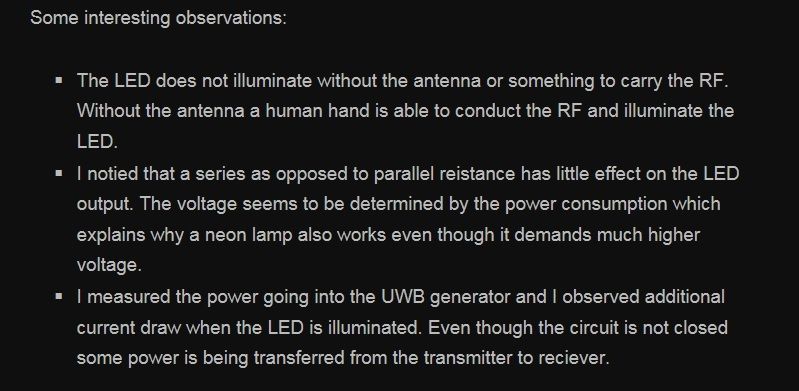 [/IMG]
There's some further info on principles, relating to the work of Doc Stiffler and Nikola Tesla. Worth checking.
BobLeave a comment:
-
Xee2 JT With Single Wire Transmision to LEDs
Here's another simple circuit from Xee2, who has posted on this forum on and off over the years. The step-by-step building instructions are very clear for those who'd like to try this circuit out:

The setup uses a simple joule thief circuit with a single wire from the collector of the transistor to a group of LEDs and small capacitors. The return wire from the LEDs is left open. Here's how Xee2 describes the function of the open wire:It's also interesting to note that the LEDs at the end of the single wire are configured in a way that resembles an AV plug.The circuit is completed by the capacitance between the wire with no connection and the Joule Thief assembly. (video - 20 sec.)
So what exactly is going on with this "capacitance" between the wire and JT assembly? Is it in fact "capacitance" or perhaps another kind of process that involves the interaction of ambient charge?
Bob
Edit: Pictures of Circuit and Setup from YT Video
[IMG]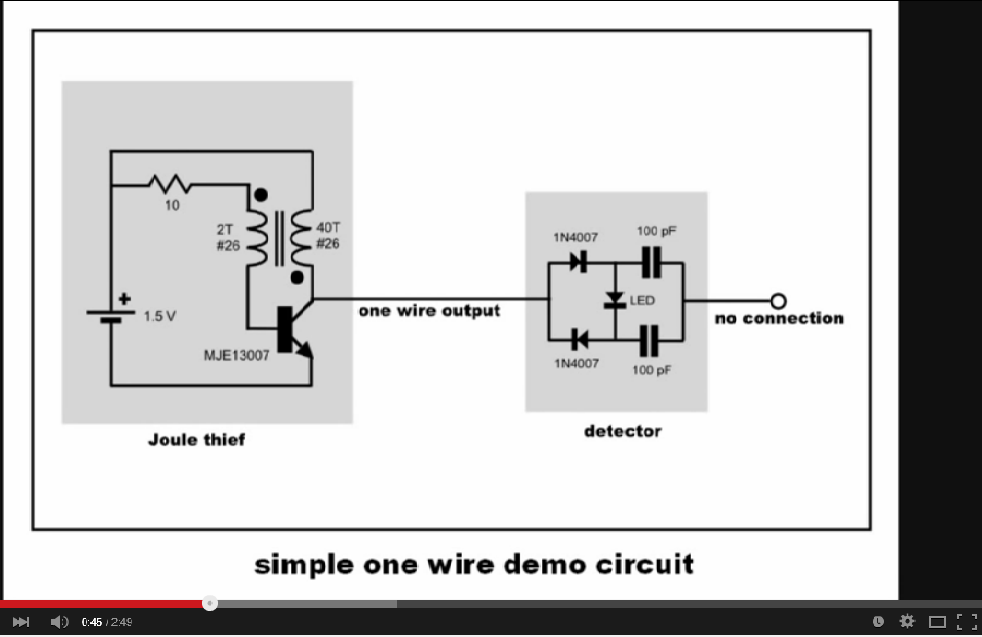 [/IMG]
[IMG]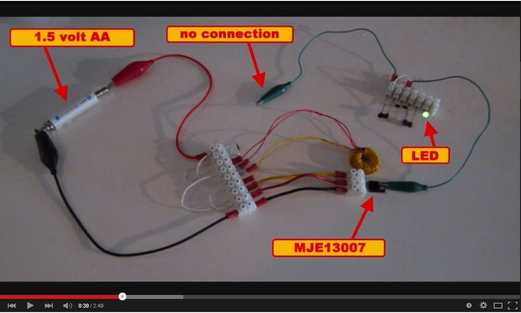 [/IMG]
Leave a comment:
-
Randy,Originally posted by tachyoncatcher View Post
Thanks for posting your thoughts and the link to the Frolov paper. If anything, I think the various kinds of setups show us that there are a number of approaches we can take to achieve SWP transmission. The AV plug also figures in Doc Stiffler's SEC. The more of these kinds of setups we examine, the better our opportunities to come up with a common understanding of the SWP effect, its development and use.
Cheers!
BobLeave a comment:
-
Avramenko's Pump
Hi Bob,
Great topic! In my opinion, the circuit in the opening post is like a radio transmitter with a led using potential created by the damped sine wave oscillator circuit and rectified by the diodes. The batteries act as a ground plane and the antenna, is well an antenna. The diode harvester is known as a Avramenko's Pump. A great white paper for potential circuits can be found here. While this circuit can be explained in conventional terms, the principals used can create some astounding results as Tesla discovered so many years ago. I believe these principals are one of the important keys to any "free energy" device.
Good Luck,
RandyLeave a comment:
-
Just thought I'd go back to this video to post the descriptor below it on YouTube:Originally posted by Bob Smith View PostThe poster talks about HF oscillation that conditions the batteries and agitates what he calls the "quantum field," which seeks to restore the imbalance (caused by oscillation) by flowing into the oscillating circuit. I would use the term "ambient realm" or "aether" or "dielectric realm" in place of "quantum field." But what's important at this point is what's actually happening. Notice the circuit has an antenna. Some would call this a virtual ground.An example of a very simple easy to build and dead cheap circuit to show to kids that only one lead is needed to have a light on.
What it in fact does is creating a high level occillation that even conditions the batteries en is capable of sending high frequency pulses that agitate the quantum field so it responses by restoring the unbalance thus creating a flow which is diverted by the two diodes that so forms a differential that makes the LED glow.
BobLeave a comment:
-
Thanks for the post and link, Mike.
I think this will be a good video to go over as the thread progresses. There are gems in there and elements that can be found in other single wire and ambient power setups. Yes, diodes and resistors do behave differently with ambient power flow versus with conventional electrical charge. Nice find.
Here are a few more to consider. What's going on?
and
and
BobLeave a comment:
-
Great thread beginnings Bob
This is what we need, we need simple learning tools and this is one
JOHN BEDINI uses all of the time. Get an energy pump/converter
running and use the double diode off one wire and collect off a
node.
Energy collectors with antenna work great around my oscillators.
This is why we use the word "Conversion" or method of conversion.
We need to start slow from the beginning of things like this. What is
going on there?
I was listening to John B way back when and he was at the chalk
board explaining this and asked the same thing. The answer is easy.
We have no idea what energy is and how it works, that is the goal
of the question. The energy will travel in both directions not just
one way even though we are taught that a diode makes it SO!!.
Aaron just showed this in his latest Gray Tube video instruction.
Aaron is well aware of most of our ignorance on this and is the
most patient instructor I know. Check out Aaron's video explaining
how the diode doesn't work like we think it does. It is charging
backwards sometimes.
It may not be a one wire experiment but it explains more than
any video or instruction I have seen this year about the nature
of energy.
Also one wire and wireless go hand and glove.
https://www.youtube.com/watch?v=lp-KOgU9n78Last edited by BroMikey; 05-22-2015, 08:06 AM.Leave a comment:
-
What's Going On Here?
Here's a link to an interesting video that demonstrates what's termed a "quantum resonant gyrator."
It's a single wire power circuit, and fairly easy to replicate:
The video opens with a question (on paper), 'what's going on here?'
Good question.
Bob
Edit: Image of setup and circuit from video-
[IMG]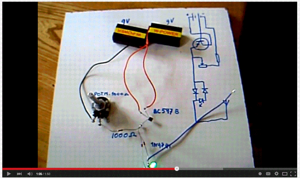 [/IMG]
Leave a comment:
-
Single Wire Power - A Search for Ambient Power to do Wwork
This thread is being set up as a collaborative investigation of single wire power (SWP) transmission. The goal is simply to arrive at a better understanding of SWP by discussing:
- various means of production and their merits
- associated effects and phenomena
- commonly agreed upon terms to describe the above.
At this initial stage, you are invited to post:
- links to videos which claim to demonstrate SWP
- links to research papers about SWP
- discussion on merits of posted information and approaches.
Later, we will seek:
- to organize electrical terms and effects surrounding the SWP field
- to identify some simple and safe approaches to producing SWP effects for further experimentation.
Some ground rules - if you decide to post, please respect the following:
- keep discussion/debate focused on principles and not persons
- honor one another’s posts
- allow for a divergence of viewpoints, frames of reference and terminologies, given that this topic spans more than one electrodynamic paradigm. It’s okay to agree to disagree, but let’s do it respectfully.


Leave a comment: