This forum is preserved as a permanent archive. The community continues at eMedia Press.

Announcement

Collapse
No announcement yet.

Hogan and Jakovlewich overunity generator

Collapse
X
 
  • Filter
  • Time
  • Show
Clear All
new posts

  • Hogan and Jakovlewich overunity generator

    Hi all,

    There is a spanish patent about an overunity generator filed in 1955 by David Hogan and Carlos Ludovik Jakovlewich (patent ES0225316) where authors clearly claim overunity performance. In this patent the intermediate "coil" is motionless and two moving magnets excite the induced circuit, one in each side of the intermediate "coil" (or "grid" as it is called in the patent text).

    The only surprising feature is that induction is forced to appear between two opposite magnets (poles facing north-south) exciting an intermediate "grid"
    CLAIMS SPANISH PATENT ES225316


    The authors claim in this patent:

    1) New electric generator characterized by the existence of series of discs, variable in number and in dimension, susceptible to host "magnets".

    2) New electric generator according to claim 1 characterized in that the series of discs are mounted on a shaft in parallel arrangement ; the shaft rests on its sides over bearings. This arrangement of supporting bearings allows its extension if required.

    3 ) New electric generator according to claims 1 and 2, wherein the "magnets" located in the discs must be placed parallely on the shaft. These discs, spaced, will allow that the poles of the magnets (magnetos) of each disc are facing "north-south" (opposition of poles).

    4) New electric generator according to claims 1 to 3, characterized in that between the discs (series of two) a stationary or fixed screen or sieve (grids) of copper wire or any other electroconductive material, enamelled and covered with insulation, is placed.

    ----------------------------------

    In the description it is clearly stated that the authors are describing an overunity generator where a part of the energy produced could be used to power the machine and the rest could be used externally for other uses.
    .

    Link to the whole patent text and figures translated into english: PDF file

    Link to spanish patent text: PDF file


    Link to patent drawing: JPG File

    .
    Attached Files
    Last edited by hanon1492; 08-27-2014, 05:30 PM. Reason: Image linked
    https://figueragenerator.wordpress.com/

  • #2
    axial flux design?

    So is this similar to an axial flux design generator? I have built axial flux alternators and they are similar to Muller and Adams and RomeroUK's ou gens.

    Looking at the diagram, it is pretty vague but looks to be built as an axial flux with no magnet gaps. Also the coil or "grid" illustration really doesn't help all that much.

    Comment


    • #3
      BETWEEN TWO OPPOSITE MAGNETS.http://www.alpoma.com/figuera/figuera_30376.pdf


      (Sketch by Ufopolitics , posted on Figuera thead)
      https://figueragenerator.wordpress.com/

      Comment


      • #4
        Attached Files
        Last edited by hanon1492; 09-22-2014, 10:37 AM. Reason: Added image
        https://figueragenerator.wordpress.com/

        Comment


        • #5
          @Hanon
          It may be a play on Earnshaw's theorem, the law states any dipole in a dipole system is inherently unstable due to the inverse square law. Now if the magnetic system as described is inherently unstable in nature then the laws which supposedly govern the actions we would normally expect may not always apply due to the fact it is fundamentally unstable. Read between the lines, Instability means we cannot accurately predict what will happen in every given case.. which is what were looking for isn't it?... something different.

          AC.

          Comment


          • #6
            Excelente Patente Hanon!

            Hello Hanon,

            Ever since you presented this Patent to me plus the Figuera's Generator one, it started a specific sector of my hard disc-brain that has never stopped working on it...even though all other work am still going through.

            I believe once We get the "essence" of this patent here...and just interpret the way they are generating induction...only then we could play with the Magnets or Exciters (Field Stators) in order to move this application in a 3D Volume.

            This Patent is great, except that they are rotating the huge flywheel of magnets in order to get Induction at the "Grid" or call it simply "windings"...

            On the Figuera's Patent I love the idea of just turning the Copper Windings with some insulation as well as structure "drum" sandwiched between inner-outer exciters or Field Stators like you have shown above. The major issue on Figuera's is to easily build a Model that complies with this...and it is not simple. Plus there was "something" still not looking good there.

            However, looking at this patent here...and like I mentioned above...moving components in 3D...untill we make them Radial, not axial like they are showing...then we could easily "fuse" this two great patents into just one...that contains the great attributes from both.

            I thought about making a separate Thread about a Fusion of Figuera-Hogan-Jakovlewich Generator
            Principles for the Development of a Complete Mind: Study the science of art. Study the art of science. Develop your senses- especially learn how to see. Realize that everything connects to everything else.― Leonardo da Vinci

            Comment


            • #7
              Decomposing Hogan-Jakovlewich Matrix 1

              Hello Hanon1492,

              Like I mentioned on previous post...here is my analysis on the way I interpret this Patent.

              First We must realize that ALL Patents are written "As General and simple terminology as possible", this way the main essence, main idea, comprehends a wider scope, not limited by specifics...This way Law Firms could assure a stronger Intellectual Protection of the Main Idea.

              This Patent, besides being written in very general terms, it does not contains a heavy description of magnetic vectors, lines of force, wire loops shape/design, etc,etc.

              Then there is a lot to "assume" here...in order that based on our knowledge we could understand how it works.

              I have read this patent in my Native Language many times...trying to find a "key word"...or any expression that would make Us understand it better...

              Text Interpretation:

              1-One Key Spanish Word they use, and I consider very important is MAMPARA, which is an old and rare Spanish term, no longer used that often.

              Mampara means "Division Wall" between two spaces, but also and mainly is considered an Insulation (Aislante)This makes a lot of sense when we try to interpret the B-Fields on this Generator Concept.

              2-B1.

              If We try to understand Induction on Coil/Grid, based on this B-1 Field, it does not make sense, right?...the Induced field vectors would be canceling each others. And this will fall into a "Non Working Device"...

              But, notice We also have another "Lines of Force", another B-Fields there, which is not exactly "straight" in shape, but defined by a curved spline traveling from North to South as well...and I defined it as B2.

              This B2 Fields DO create an Induction FLOW on Coil Loops interacting with each surface of both discs (considering the Grid consists of "Diametrical" wire loops, related to Axis.

              And here the word Mampara (Insulation, Division Wall) comes to play the main role.

              Only if We Insulate, Divide, Obstruct the two B1 Fields, magnetically...Only then, the predominating B2 Fields will effect/Induce the coils and this device will work perfectly well.

              [IMG]FIG IV of Patent (from FIG 1 to FIG 2)

              FIG 3 shows the start of decomposing the Coils and magnets in order to make them "RADIAL" as seen on FIG 4.

              As You can notice B2 takes the place of B1

              And, no matter if We rotate Magnets or Coil...the main B Fields that would be causing a DC Induced Flow would be the same that caused Flow on previous FIG 1.

              Therefore, on FIG 4 We must isolate or block B2 Fields to allow only B1 to cause induction flow.

              The reason to transform this original patent into Radial...is to be able to add/fuse with Figuera's Main Concept, where He uses a Central/Inner Exciter...


              To be continued...


              Regards to all


              Ufopolitics
              Principles for the Development of a Complete Mind: Study the science of art. Study the art of science. Develop your senses- especially learn how to see. Realize that everything connects to everything else.― Leonardo da Vinci

              Comment


              • #8
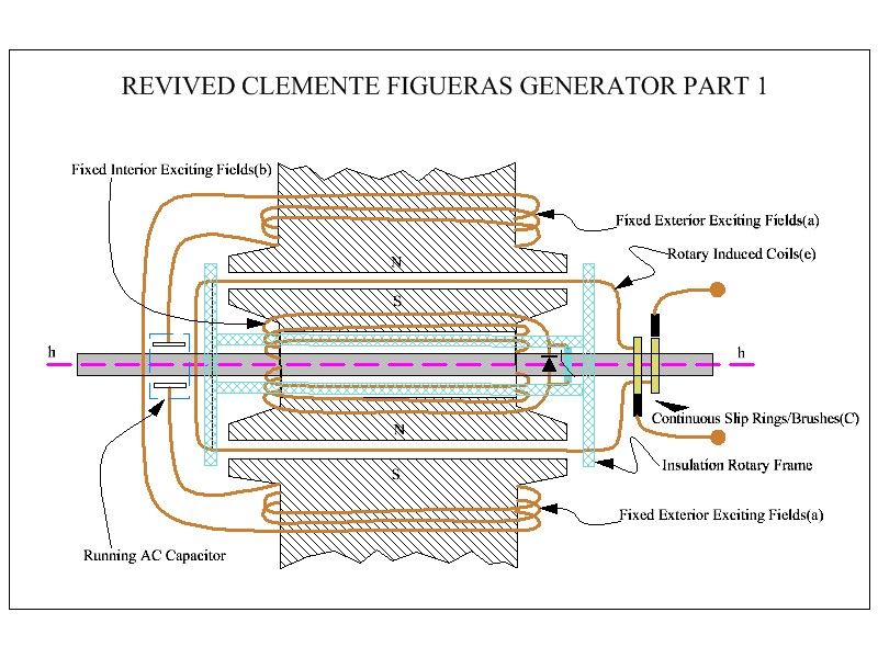
                Hogan-Jakovlweich-Figueras Fusion Part 1

                Hello to All,

                Ok, from previous and last Diagram (FIG 4), We continue here...

                [IMG][/IMG]

                2-I have set Two Layers of Coil Windings (Green and Gold), and have only represented here start and end of sweeping Coils[/IMG]

                If We can achieve Induction Flow by running a wire over this type of set up, where North is above and South below...or viceversa...cutting this magnetic lines of force...then this design would have an incredible potential of Generation. And due to set apart by 90 degrees Inner and Outer Exciters...it will not be a face to face that would create opposition when loaded.

                Building this would be pretty simple...by using Curved Magnets from Motors, and finding the right circumferences, inner and outer...
                The Rotor Structure could be made first of an upper and lower salient teeth pattern, just like Rotors in motors...but made out of plastic or fiberglass, just to guide each coil windings in place, however, copper wires would be completely "exposed" in front of Exciters-Stators.

                Member Machine Alive on another Thread designed the way to do this with rotating the outer end of bearings for rotor, while having a stationary shaft attached to inner bearing collar...very smart design there!.

                I need to make a 3D CAD of this Model, to see it better...it is pretty complicated to see it all in 2D.


                Thanks again Hanon1492, and regards to All.


                Ufopolitics
                Last edited by Ufopolitics; 08-05-2014, 07:12 PM.
                Principles for the Development of a Complete Mind: Study the science of art. Study the art of science. Develop your senses- especially learn how to see. Realize that everything connects to everything else.― Leonardo da Vinci

                Comment


                • #9
                  Patent translation

                  Hi all,

                  I have translated the whole patent text from the Hogan Jakovlewich document into english in order that anyone may read it and understand it.

                  Please have a look. Really interesting !!!

                  Patent text in english

                  Regards
                  https://figueragenerator.wordpress.com/

                  Comment


                  • #10
                    Link to pdfThe key for avoiding dragging is the use of two opposite poles to generate the induction in the intermediate wirebased also on the induction created between two electromagnets, instead of common induction with just one pole exposed. IMHO, This is the key of his discovery.

                    I attach an sketch with the representation of this principle. Please study this sketch and tell your comments. Both patents (Figuera and Hogan & Jakovlewich) share the same principle, and both patent are representing an overunity generator withoudt dragging. Please have a look into Figuera thread in the next link: Figuera thread


                    Link to sketch of no drag principle: No dragging principle between two magnetic poles
                    Last edited by hanon1492; 08-27-2014, 05:28 PM. Reason: Image linked
                    https://figueragenerator.wordpress.com/

                    Comment


                    • #11
                      https://figueragenerator.wordpress.com/

                      Comment


                      • #12
                        This video collect the foundation of these devices:


                        https://www.youtube.com/watch?v=dtiMQPeYJrQ
                        https://figueragenerator.wordpress.com/

                        Comment

                        Working...
                        X