If this is your first visit, be sure to
check out the FAQ by clicking the
link above. You may have to register
before you can post: click the register link above to proceed. To start viewing messages,
select the forum that you want to visit from the selection below.
Hi guys watching this video from one of the greatest invention of our time..THANK YOU MR SKINNER WHERE EVER YOU ARE IN THIS UNINIVERSE..THANK YOU and thank you to the guy who put this video to our attention.. I am going a different path , I have send this video to an engineering firm in western Australia to reverse engineer it ..I told the guy there I do not care how much it cost I will see it COME TO A WORKING PTOTOTYPE..Yes I might be a fool I am 52 years old I have seen a lot of very interesting invention in my life time but this one is PURE GOLD .. again THANK YOU MR SKINNER WHERE EVER YOU ARE IN THIS UNIVERSE..
Hi guys watching this video from one of the greatest invention of our time..THANK YOU MR SKINNER WHERE EVER YOU ARE IN THIS UNINIVERSE..THANK YOU and thank you to the guy who put this video to our attention.. I am going a different path , I have send this video to an engineering firm in western Australia to reverse engineer it ..I told the guy there I do not care how much it cost I will see it COME TO A WORKING PTOTOTYPE..Yes I might be a fool I am 52 years old I have seen a lot of very interesting invention in my life time but this one is PURE GOLD .. again THANK YOU MR SKINNER WHERE EVER YOU ARE IN THIS UNIVERSE..
I'm not sure what it will prove.
I think the meters would tell us if there is any gain from a
full scale build using this principle.
It might tear apart the enclosure if you turn up the voltage too high.
You could see if less input voltage could drive it as well as the voltage you've been using.
I'm in uncharted waters.....
Tom
Luc,
In your latest version is the lever rod free to rotate inside the bearing at the top of the lever rod...the one on the drive wheel? or is it fixed so it can't?
Tom
Yes Tom, the top lever is free to turn in the top bearing I specially made which is attached to the drive wheel. Made it that way from the very beginning.
Luc,
In your latest version is the lever rod free to rotate inside the bearing at the top of the lever rod...the one on the drive wheel? or is it fixed so it can't?
Tom
I can't make a video right now.
I see gotoluc over on the other forum has beat me to it.
see his 2 private videos on page 15 and 16.
they pretty much get across what I'm talking about although there
are some differences.
Tom
Hi everyone,
I have not been posting at this forum topic because I didn't want to disturb Aaron's suggestions since I was not convinced of the mechanics of Mr. Skinner's device.
First I wanted to try some things that I observed which were different then what Aaron was suggesting. I'm not going to go over it here so you would have to read the OU topic to understand the reasoning.
I have made those tests and have eliminated those possibilities and now mostly agree with what Aaron has shared as to the mechanical movements needed.
Here is the links to my first test video with NO universal joint to the bottom shaft and a circular movement to the upper leaver.
Here is the link to my newest test video WITH universal joint to the bottom shaft and a circular movement to the upper leaver. Notice I can stop the rotation of the two shafts and the top lever rotation plate continues to turn freely. So a bearing in the mid plate may not be needed.
With the universal joint added the device performs more like seen in the original Skinner film but the load is still reflected back to the prime mover. I tried everything I could think of and finally decided to take the upper lever out of the circular drive and turn it by hand while the bottom generator is under load (bulb).
By turning the lever in a circle motion I could feel an equal pressure throughout the 360 degrees and the bulb load would not light.
By turning the lever in an elliptical orbit the top weight would fall and cause a change in angle to the mid plate which would make the bottom weight swing around and the bulb would light for that moment. There is a pressure point at the turning points of the elliptical orbit but there is also an acceleration when the top weight falls, so it may come close to being neutral to the prime mover (other than friction losses) but this remains to be tested.
Now looking for recommendations on how I can easily convert my top gear so the lever is turned in an elliptical orbit to further test this possibility of being the right thing.
I will now post future video and updates to this topic as I'm now going the same direction that Aaron has started the topic with.
Thanks very much for that video.
It makes me wonder if instead of a clutch Skinner used an epicyclical gear train and the lever he grabbed altered the planetary arrangement to give a different ratio/speed to the input rod levers after the whole machine had started to turn slowly.
I'd like to ask about Jim Murray's ideas. At one point on his video he talks about the model he built that looks like a motor with a bent or flexible shaft that went out and connected to the perimeter of a larger wheel. He said that if the motor shaft went around once the other end of it went around twice and that it was a physical impossibility. Or words to that effect. point of reference was all important...etc . Can you elaborate on that and can we use it in the machine or are you already using it and I haven't noticed?
back to the meccano model.
Tom
Hi Tom,
Here's a video that explains the epicyclic effect that Jim Murray observed. Skip to the part with the two coins and you'll see the 2:1 relationship.
I can't make a video right now.
I see gotoluc over on the other forum has beat me to it.
see his 2 private videos on page 15 and 16.
they pretty much get across what I'm talking about although there
are some differences.
My intuition tells me I don't have it quite correct and I need to introduce more loosly coupled ideas instead of directly coupled.
I went back to the beginning and rewatched your whole video again.
I'm still concerned that the lever tip in a gimbal won't start the machine.
If it's spinning just a bit then yes I can see it would accelerate it and keep it going but starting it??.
I noticed also that filming the starting is missing. I might conclude that
it took a while and the camera guy didn't want to waste time on it.
watching the film for the millionth time I noticed that the translation plate only looks to be about 4" square or so. It's about the size of skinner's hand.
Maybe a key to the machine's successful working is that the offset between the lever tip and lower weight top is kept quite small. Maybe my model is offset too much. In twirling the lower weight model around by hand I know that I can get it spinning faster with less tilt, but we have to get it started and going with a bit more tilt.
There sure is a lot of different variables and math to consider to come up with a working machine but if Skinner did it then we should be able to do it too and come up with improvements once we grasp all the important details.
I'd like to ask about Jim Murray's ideas. At one point on his video he talks about the model he built that looks like a motor with a bent or flexible shaft that went out and connected to the perimeter of a larger wheel. He said that if the motor shaft went around once the other end of it went around twice and that it was a physical impossibility. Or words to that effect. point of reference was all important...etc . Can you elaborate on that and can we use it in the machine or are you already using it and I haven't noticed?
Aaron my idea is to transmit mechanical energy form the rotation of lower output weight directly , i know there is an oval , but this oval i am not sure if there going to be a big degree or not, But this is not a problem ,i think this should be determined by experiment
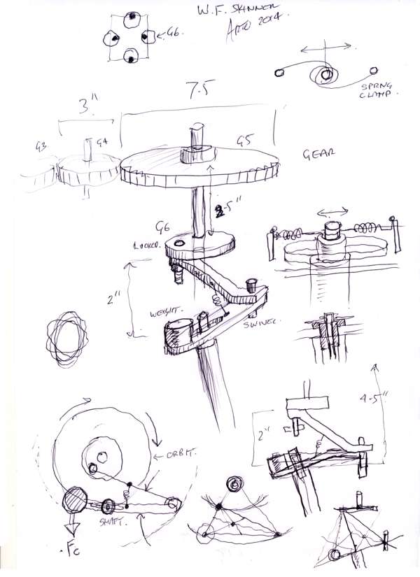
Hi all, here is another sketch that might help nail the Skinner mechanism. I am following a the simple idea that friction and force are this machines worst enemies, where a balance of reactions on the top shaft can be made to be feather light while the fulcrum length has a force advantage of about 4:1 to the middle wobble plate where the gimbals are the fulcrum.
So the most important area for least bearing torque loading will be the top wobble plate. The gears are simple and efficient way of transferring the rotations in all 4 directions while allowing the correct offsets so that the spinning weights can maintain a balanced action in synchronicity, Left-Right->out from center and front-back->in to center.
Regarding the top mechanism, the use of the correct bearings will allow the internal bearing loads not to have force vectors beyond the admissible misalignment, thus loading the required actions and creating the incorrect geometry. Using only shielded and high clearance C3 types, these should give you a better misalignment characteristic while allowing higher speed without added heat and losses. Where possible a sintered bush for any combination of rotary linear action is workable as the type of rotations are low and the loads are not at right angles to the bearing face, acting simply as guides not a load bearing action.
The use of a plain self-aligning bearing(GE series) or a externally self aligning type(UC series) is the least satisfactory avenue, the best type is a double row self aligning ball bearing or spherical roller type, a 1204 is 20mm x 47x 14, the only problem is, that it is not shielded, while an open type can be pushed to a 5 degree misalignment, the sealed unit will only give you up to 2.5 degrees of misalignment, while the seals will create added torques as well.
These sketches are probably of no value to the builders as they have already made up there minds of how to approach the problem, I like to include them as a record of ideas, which now are piling up to 3 x 120 page books plus about 100 A4 pages and not to discount the 60 odd files of data that fill up my hard drive, these are the only ways I can approach a build, 95% of the guess work removed long before I spend $1 on parts, as $1 is more than I have anyway. I hope my efforts are of some value to those following this thread.
Hmmmm.
Maybe my previous meccano attempts were built wrong.
Here's what I discovered...which maybe the wrong way to build it ?
I have a meccano model built now that works just like the video but here's how it's different than what you're suggesting:
Up at the very top of the machine:
The top horizontal wheel/gear (I'm going with a wheel/gear up there rather than an ellipse maker) has the top of the input lever arm attached to it's lower face out near the perimeter. that wheel turns on a vertical axle which is connected back through whatever way to the electric motor. The top of the input lever arm
can be welded, bolted, clamped or hinged to the wheel but the input shaft can't turn/spin on it's own axis. Probably hinged would be the best to allow for any slight wobble of the wheel as it turns. the hinge pin being perpendicular to a line drawn from the wheel hub out to the hinge.
3/4 to 7/8 of the way down the input lever rod (or thereabouts) it passes through a gimbal bearing that is free to rotate and wobble.(like the decaying motion of a dinner plate spun on it's edge on a table before it ends up flat)
then the bottom tip of the input lever rod goes into the translation coupler plate and is fixed to it (welded, bolted or otherwise captured by it) so it can't turn on the tip of the lever rod. However the hole in the translation plate is drilled at an angle which is the same as the angle formed between the top wheel and the top of the lever rod. This allows the translation plate to rotate in a plane parallel to that of the lower face of the upper wheel. (skinner might not have got that angle quite correct and that's why the plate wobbles a bit)
Looking at it from the side if the lever rod is all the way over to the left at the top, then the translation plate and it's weight sticks out way over to the right.
The motion of the lever rod is hard to describe....I call it funneling.
The lever rod's motion through the air above the gimbal forms the shape of a funnel.
The top of the input lever rod orbits (like the moon) but the part that goes through the gimbal (x/y pivot) turns/rotates. What is the correct word to use? It's not spinning on it's own axis but it is rotating in it's own fashion. The center of the top wheel and the center of the gimbal pivot must be vertically in line with each other.
The rod forms the shape of a small cone through the air below the gimbal pivot.
Therefore the translation plate moves in a circle as does the lower weight's shaft.
On my model built as above, it whips the lower weight around just fine.
I may have to make the lever rod a lot longer than I currently have to magnify the leverage enough. My current model just has 2 shafts instead of 4.
Doing it this way ensures all 4 upper weights stay in step with each other as they can be geared to a central shaft and then back to the motor. Also the translation plate has no chance of not moving the upper weight.
This method also explains why I can see (in the video) the lever rod closest to the camera is rotating.
As always.. I may have it all wrong. What do you think?
Tom
Last edited by goldpro; 06-22-2014, 01:01 AM.
Reason: clarification


Leave a comment: