This forum is preserved as a permanent archive. The community continues at eMedia Press.

Announcement

Collapse
No announcement yet.

COP 20.0 (2000%) Demonstration

Collapse
X
 
  • Filter
  • Time
  • Show
Clear All
new posts

  • Modified sine wave

    Originally posted by tachyoncatcher View Post
    Great job Mike. I'm going to pollute it with one crappy image to give my interpretation of this wave form. I have superimposed where, I think, the original, unbroken sine wave is. At the top is numbers to represent what I feel are important events in this image. Comments below image.

    1. First quadrant ( quarter ) of the sine. Terminated with first switch.
    2. Flyback from first switch off.
    3. Switch off with pause (important).
    4. Down side of sine terminating with switch off.
    5. Flyback from switch off.
    6. Final pause.

    When I say switch off I am referring to as it relates to the source. They obviously are redirecting between input, caps, gen coils, and output. Using the switches to change the circuit from gen/rlc/load to motor/load. Remember, they load both directions.

    That is my opinion of this wave form though I could be WAY out there. Please correct my understanding if I am.

    Randy
    Hello Randy

    Yes thanks very much. I have revised your wave to reflect all of our posts and by keeping the material before our eye we made indeed replicate some sort of off shoot of this tech.

    At first I didn't really see the wave like you had shown.

    Here is a small tweek.


    Mike

    Comment


    • Output wave Quardrants

      Also for those of you pondering these waves keep in mind that there are two output waves coming off of the standard style isolation transformer with half of the core removed.

      These two waves coming from the transformer are sort of modified sinusoidal wave that are adjusted at the front end processor switching platform so that the each wave takes on a life of its own and can coincide with each other, intersecting plus overlapping one another's space to produce these phenomenon. Not to mention the tilted formations on his scope shot in the video.

      The output driving the lamps is again changed to form a pulse train of dc yet has 3 waveforms as shown in the board drawings.

      Here is only one set of the 3 output waves that are all about the same as far as I can see.


      Mike
      Last edited by BroMikey; 07-26-2014, 08:53 AM.

      Comment


      • Comment


        • Also guys, the falstadt simulator does NOT show what's going on in real world.

          Simulate a resonant tank circuit fed by the usual source in parallel. At resonance it will show almost no current going from the source to the tank, which is correct.
          Now modify it and replace the inductor with a transformer like you guys did and have the source feed the primary while the secondary goes directly to the cap.
          Now at resonance the simulator shows current going through the primary. In the real world the current through the primary from the source is just a tiny bit more than the directly fed tank above.(transformer losses).
          The same setup with a switched tank should get almost nothing through the primary.

          I really appreciate the simulations that have been done, but I wouldn't rely too much on its accuracy. Real world experiments are needed...

          regards,
          Mario

          Comment


          • FWBR Wave Shapes

            No I didn't realize that Mario

            Hey the board drawings show 3 sets of waveforms and the lower one has a much shorter peak value on the right hand pointy wave shape. I can read the writing "yet" on that board drawing so I don't know what it says by each set of wave forms.

            Good to hear of your entry into this experiment

            Mike
            Last edited by BroMikey; 07-26-2014, 08:55 PM.

            Comment


            • Hi all,

              I think a light went on, for me at least. When I started this project I always thought in terms of tank circuit, meaning "real" resonance. A matched coil and cap that can hold the same amount of energy at a given frequency and just shuttle the energy back and forth. If your coil is the secondary of a transformer, in your primary winding there won't be hardly any current.
              The whole time I was working on this SERPS switching circuit trying get to a point where there wasn't any current in the primary. I thought that was the goal because I was seeing that my audio amp supplying the transformer primary was still consuming watts.

              Now I've realised that my circuit is working perfectly, I do not have to worry about not having current in my primary. All I have to worry about is to have the difference between positive and negative amp pulses in and out close to zero.

              If instead of my audio amp being the source I would have my circuit connected to the mains (which I can't because I don't have the 0 crossing circuit yet that syncs the circuit to the mains) I would see the same thing on a wattmeter as Jim Murray.

              In fact the problem is the source. Even though on my scope I see the same amount of current coming in that's going back my audio amp doesn't know what do with it because it doesn't work like a generator. A generator act as a generator for one moment charging our cap through the load, then our cap discharges back through the load to the generator making it become a motor for a moment. This is why on the shaft less energy has to be supplied.

              The question is, if we want to stay solid state without having to use a generator, what kind of AC source can we use?

              Sorry if this was already obvious for many of you.

              regards,
              Mario
              Last edited by Mario; 07-26-2014, 04:44 PM.

              Comment


              • Popcorn Chinese Geneset

                Originally posted by Mario View Post
                Hi all,

                I think a light went on.............................

                Now I've realised that my circuit is working perfectly, ..........................

                In fact the problem is the source.


                Even though on my scope I see the same amount of current coming in that's going back my audio amp doesn't know what do with it because it doesn't work like a generator.


                A generator act as a generator for one moment charging our cap through the load, then our cap discharges back through the load to the generator making it become a motor for a moment.


                Sorry if this was already obvious for many of you.

                regards,
                Mario

                Hey that is great Mario

                I will let the others guys talk now that have more experimental background with the SERPS, but before I do let me say this. If you are getting a certain waveform that you believe is equivalent to the SERPS wave please post it for us at your nearest possible convenience.

                The other important thing I need to mention is that where I live FARMER have Gensets in the field or they will have a motor using a gas like propane where electricity can not reach.

                The point is that I wonder if you understand the implications here? You are saying that all you need to test your circuit is a popcorn peanut chinese genset? Well that is nothing, someone who is watching would give you one of those if they thought you really had the SERPS gen circuit.

                My brother had 3 or 4 just setting around and got rid of them.

                I understand how we are all well able to get whatever we need to complete any job OVER THE COURSE OF TIME, but what is wrong with a little help?

                I'de like to see you get one of those small gensets like ANTON has (THAT GUY IN GERMANY) running on HHO 100 percent powered off the closed loop system.

                One time I ran out of gas (Or so I thought) and went to buy some. I put it in the tank and nothing happened, just starter noise. So I pulled the fuel line and found that the pump had actual stopped and since my gauge read low I just assumed the wrong problem.

                I looked around the truck (It was an old 90's Dodge RAM) and found an empty clear dish soap bottle and a hose. What do you think I did?

                I still had some in the large jug of gas and I only needed to go 12 miles, so I put some gas in the soap bottle stuck the hose down into it and ran the other end to the carburetor I had on it from and old Maverick.

                I am a mechanic Sir. I have worked on the finest cars you can think of, well I was lucky that day because I had a carb and not injection so I set up the bottle on the dash (don't try this at home ) and hit the starter.

                Off down the road I went to the house but I was able to see my fuel consumption now looking through the clear bottle. Closer and closer I got to the house and the gas was going bye bye fast out of that tiny make shift tank.

                The point being is I have run tests like this to watch and measure gasoline usage by making lines with a marker and watching the time to get a relative idea. I have one Genset that is a 40hp Wisconsin skid loader type air cooled motor that when using gasoline it takes more gas than when I use propane.

                These are the proper tests that need to be made. Set your stop watch measuring the load and you will have your answer. I remember back when i still had babies and I didn't have piles of money to spend on anything.

                I spent $100 on baby supplies every week. I think someone could send you a genset, that is a small thing.

                Then you stated you would need a ZERO CROSSING circuit?

                I have no idea of your life arrangement, all I am saying here is that it is time we share in this work to help one another and the first thing that needs to be done is that we let each other know of the need.

                Also on another note:I can go to the dictionary and remind myself of the ZERO CROSSING circuit, but I can't think right now where it fits into the circuit.

                Hey Mario I built my own Genset out of an old rototiller side shaft engine and hooked that to an electric motor paralleling 300 uf of oil filled capacitors.

                I can run a 7 amp load off of that motor acting as a generator.

                You may not have the time or the resources to pull this job off without some help.

                Great work Mario and I think you'll have it now.

                Mike
                Last edited by BroMikey; 07-28-2014, 02:13 AM.

                Comment


                • Motor Generator

                  Here is a guy who did the same thing to get a pure sine wave.

                  induction motor generator 2 0f 2 - YouTube

                  Mike

                  Comment


                  • Comment


                    • Ok, found out my router was set up to block pop up windows...

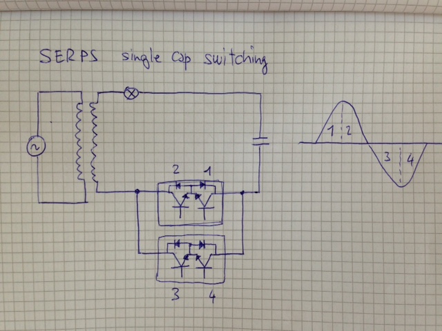
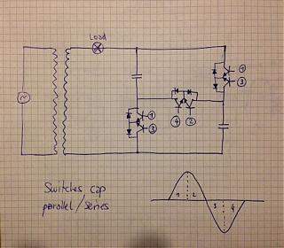
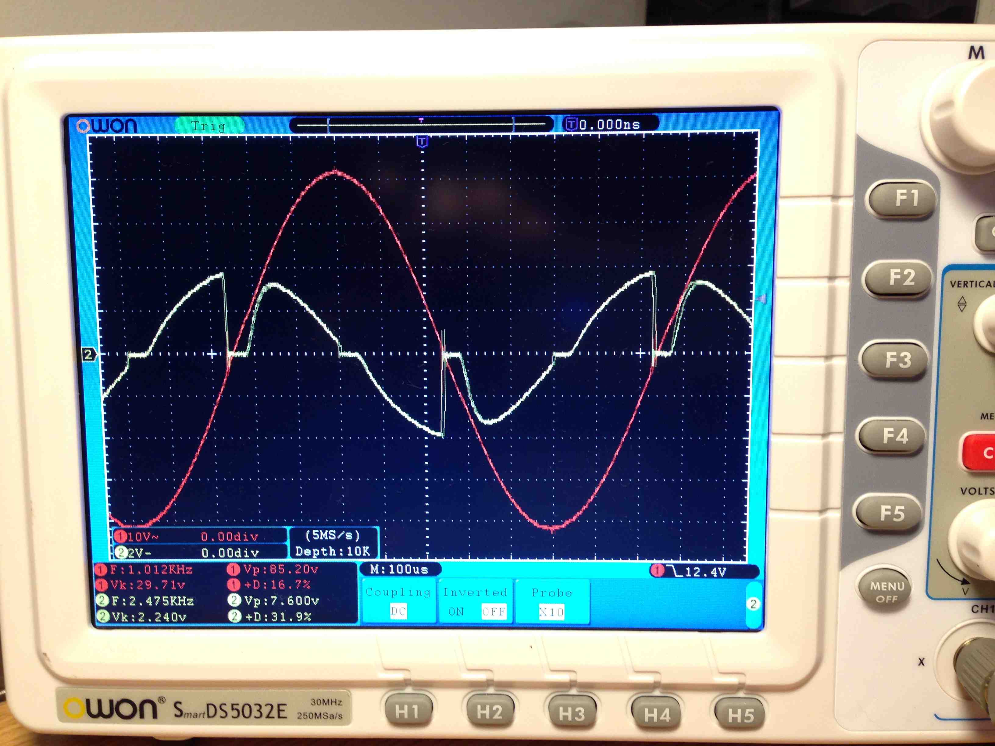
                      Attached you'll find very bad drawings of my setups, both for one cap and for parallel charge - series discharge with two caps. I don't think they use the latter though. Nevermind the transistor symbols... I used mosfets.
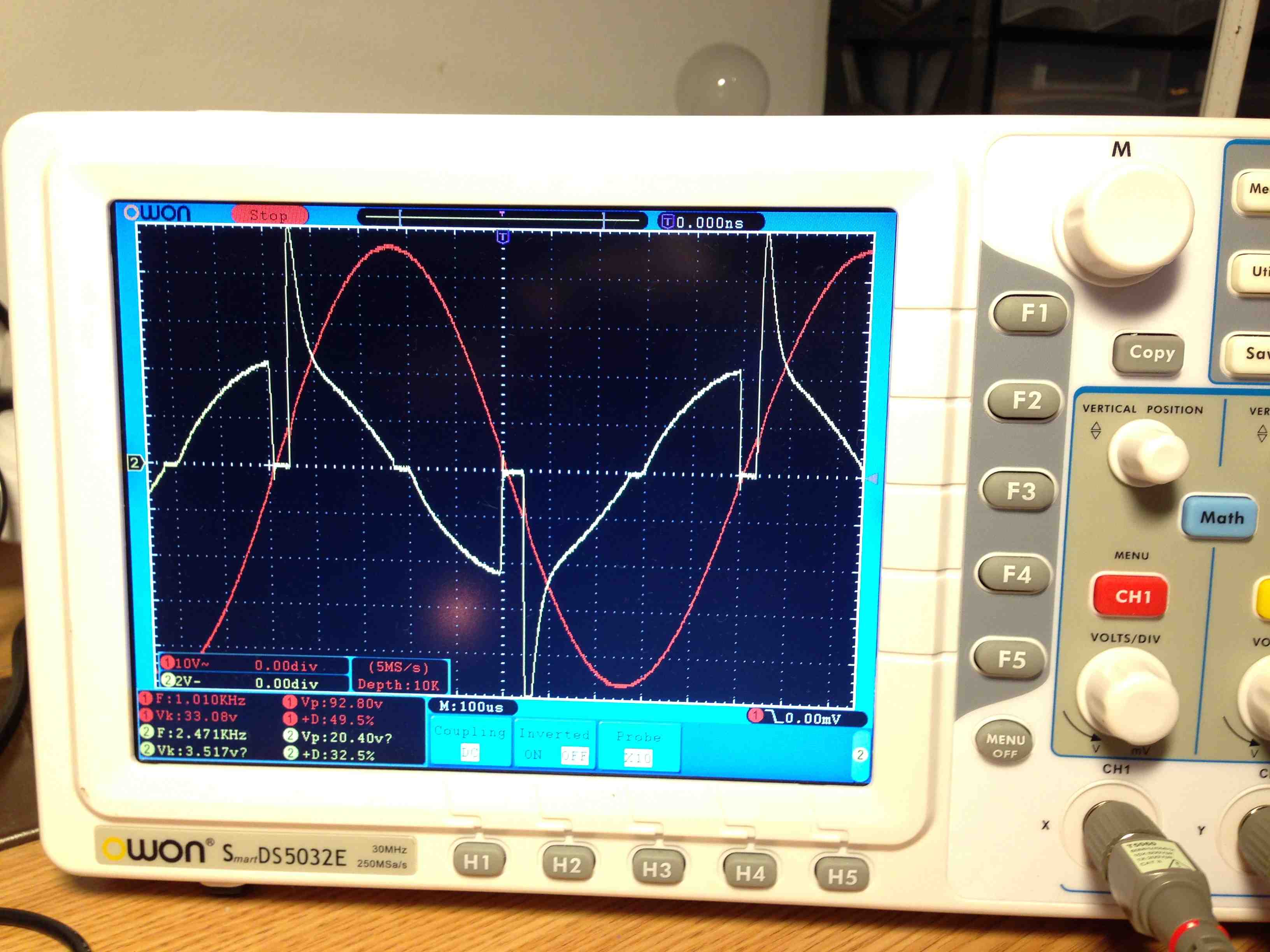
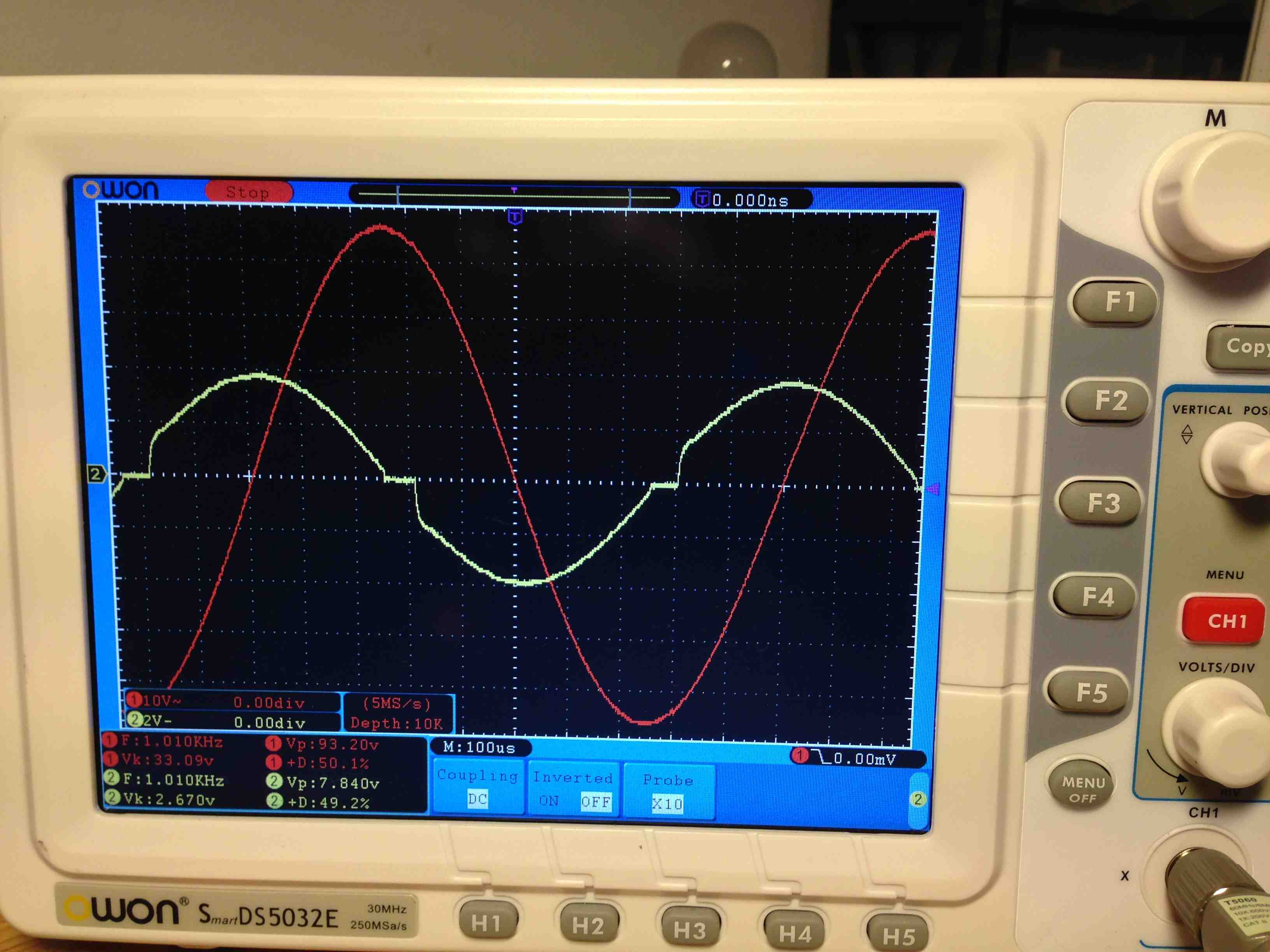
                      In the single cap setup one switch would be enough but I had to put two in parallel because I couldn't sum the drive signals. Also a couple scope shots, where you can see current with regards to input sine wave.

                      regards,
                      Mario
                      Attached Files

                      Comment


                      • Hi Mario.
                        Your case with switching one cap with bidirectional mosfets or SSR looks like coil shorting at peaks ala Ismael Aviso

                        Comment


                        • Originally posted by kEhYo77 View Post
                          Hi Mario.
                          Your case with switching one cap with bidirectional mosfets or SSR looks like coil shorting at peaks ala Ismael Aviso
                          Hi, no, that's not it in this case.

                          regards,
                          Mario

                          Comment


                          • coil shorting SERPS

                            Originally posted by kEhYo77 View Post
                            Hi Mario.
                            Your case with switching one cap with bidirectional mosfets or SSR looks like coil shorting at peaks ala Ismael Aviso
                            Yes coil shorting right!!! The coil is being disruptively knocked off of it's pirch and shorted out some but not a dead short. When the cap hits the coil winding at that phase angle it semi-shorts out the energy present in that portion of the wave but in this case absorbs it.

                            The coil winding wave is being semi-shorted out the energy is then collected unlike true coil shorting does wasting that energy. The SERPS harvests the coil shorting energy.

                            I see it now thanks guys for batting the ball back and forth.

                            Coil shorting is said to take place all around the peaks of the sinwave both above and below the zero line. The SERPS is shorting coils as they go toward their peaks as well and just past the peaks again, so it is very similar in that aspect.

                            However saving the energy in caps to re-inject later may look some what like true coil shorting on the scope but is a much more complex process.

                            Great going Mario. You are a genius. I think you said you could tell that something over and above the ordinary was feeding back to source and know that this is the WAY!!

                            Mike
                            Last edited by BroMikey; 07-29-2014, 03:29 AM.

                            Comment


                            • Wave comparisons

                              Here are the two waves we have been looking at.


                              Great job so far Mario.

                              It looks like one wave is 90 degrees out of phase from the other. That may not be the right place to put the sinewave for the first wave.

                              Mike
                              Last edited by BroMikey; 07-29-2014, 04:27 AM.

                              Comment


                              • Phase Comparison

                                It looks like we have a phase difference. Here is a sloppy line drawn to show phase difference. The question is "Did we assume the wrong phase relationship"?


                                Mike

                                Comment

                                Working...
                                X