
Scale it up
$37 of course is the info but you really need to focus on a large build go get the real benefits. Newman and Miller have both built big ones that get the "Newman Effect". Small bench models only demonstrate the mechanics of how it runs.
A good question for Geoffrey, what is the smallest one Newman built that is overunity.
-
NEWMAN MOTOR DISCLOSURE INCLUDES:
 Joseph Newman Motor Disclosure by Geoffrey Miller Here is a 25% DISCOUNT coupon code: NEWMAN
EXPIRES IN 48 HOURSNEWMAN MOTOR FULL DISCLOSURE: Newman Motor Disclosure by Geoffrey MillerLeave a comment:
-
Joseph Newman with Johnny Carson
Someone just uploaded this and posted it in a yahoo group.
Better download this and re-upload it before it disappears.Leave a comment:
-
Are we there yet?
I'm starting to think that the Joseph Newman Machine works similar to the Windcatcher product:
[VIDEO]https://www.youtube.com/watch?v=Jv9Gghy6Lj4[/VIDEO]
However, instead of entraining the air into a bag through a valve like the Windcatcher, the Joseph Newman Machine entrains surrounding electrons with a combination of flyback-emf and the distributed capacitance of the coil, with the switching mechanism acting as a sort of valve. Instead of excess air under pressure like the Windcatcher, there would be an increased number of electrons in the coil.
Going further: The flow of electrons into the coil would generate an excessive back-emf simply through the magnetic Lorentz force acting upon it as it moves through the coil's magnetic field, explaining the origin of enhanced flyback energy. When the electrons inevitably leave the coil, they would do so when the magnetic field is weaker, or perhaps even after the magnetic field has reversed, which would only enhance the back-emf.
If this is true, the Maxwell stress tensor would require that angular momentum be radiated to environment through the electromagnetic field. I will now argue that a circulating Poynting vector is indeed produced by the above described process, one which may in principle possess the necessary angular momentum, which is emitted.
First, take the field of an oscillating electric quadrupole, which implies an oscillating charge density due to converging/diverging currents:
physicspages.com/2015/01/25/electric-quadrupole-radiation/
Second, take the field of an oscillating magnetic dipole, which implies an oscillating circulating current.
physicspages.com/2015/01/21/fields-of-an-oscillating-magnetic-dipole/
Third, let's line both up and place them at the same center.
So the magnetic field of the oscillating electric quadrupole is azimuthal, as is the transformer electric field of the oscillating magnetic dipole. Therefore, these components are parallel to each other, so you can ignore their the cross-interaction, or rather, lack thereof.
We then only consider the electric field of the oscillating electric quadrupole:

...and the magnetic field of the oscillating magnetic dipole:Code:\displaystyle \mathbf{E} \displaystyle = -\frac{\mu_{0}d\omega^{2}p_{0}}{4\pi r^{2}}c_{\theta}^{2}c_{\omega}\hat{\mathbf{r}}+\frac{\mu_{0}p_{0}d\omega^{2}}{\pi}c_{\theta}s_{\theta}\left(\frac{\omega s_{\omega}}{4cr}-\frac{c_{\omega}}{2r^{2}}\right)\hat{\boldsymbol{\theta}}

Our objective is to get a circulating, or transverse, Poynting vector that drops with the inverse cube of the distance. The result is angular momentum flux that implies a torque exerted on the dynamic charge-current distributions responsible for said fields. This angular momentum "radiates" outward by following the inverse square law (proportional to 1/r^2) because here you perform the cross product of the the circulating Poynting vector (proportional to 1/r^3) and the radial vector from center of the source (proportional to r). We can simplify the formulas thusly:Code:\displaystyle \mathbf{B} \displaystyle = \displaystyle \nabla\times\mathbf{A} = \frac{\mu_{0}m_{0}\cos\theta}{2\pi r^{2}}\left[\frac{1}{r}\cos\left[\omega\left(t-r/c\right)\right]-\frac{\omega}{c}\sin\left[\omega\left(t-r/c\right)\right]\right]\hat{\mathbf{r}}+ \frac{\mu_{0}m_{0}\sin\theta}{4\pi r}\left[\left(\frac{1}{r^{2}}-\frac{\omega^{2}}{c^{2}}\right)\cos\left[\omega\left(t-r/c\right)\right]-\frac{\omega}{rc}\sin\left[\omega\left(t-r/c\right)\right]\right]\hat{\boldsymbol{\theta}}

Code:\displaystyle \mathbf{E}_{simp} \displaystyle = -\frac{\mu_{0}d\omega^{2}p_{0}}{4\pi r^{2}}c_{\theta}^{2}c_{\omega}\hat{\mathbf{r}}+\frac{\mu_{0}p_{0}d\omega^{2}}{\pi}c_{\theta}s_{\theta}\left(\frac{\omega s_{\omega}}{4cr}\right)\hat{\boldsymbol{\theta}}
The two source pages for the formulas prior used employed different symbols for the sinusoidal time functions. If we apply the same symbols to both, per equation 29 at physicspages.com/2015/01/25/electric-quadrupole-radiation/, we get for the magnetic field:Code:\displaystyle \mathbf{B}_{simp} = \frac{\mu_{0}m_{0}\cos\theta}{2\pi r^{2}}\left[-\frac{\omega}{c}\sin\left[\omega\left(t-r/c\right)\right]\right]\hat{\mathbf{r}}+ \frac{\mu_{0}m_{0}\sin\theta}{4\pi r}\left[-\frac{\omega^{2}}{c^{2}}\cos\left[\omega\left(t-r/c\right)\right]\right]\hat{\boldsymbol{\theta}}

As a result, the cross product is:Code:\displaystyle \mathbf{B}_{simp} = \frac{\mu_{0}m_{0}c_{\theta}}{2\pi r^{2}}\left[-\frac{\omega}{c}s_{\omega}\right]\hat{\mathbf{r}}+ \frac{\mu_{0}m_{0}s_{\theta}}{4\pi r}\left[-\frac{\omega^{2}}{c^{2}}c_{\omega}\right]\hat{\boldsymbol{\theta}}

...which is an azimuthal Poynting vector that drops with the inverse cube of the distance, producing an (orbital) angular momentum density that drops with the inverse square of the distance (ergo: angular momentum is radiated). The above gives a constant multiplied by a trigonometric function. In the case that the electric quadrupole oscillates at same frequency and phase as the AC component of the magnetic field of the solenoid (as what may happen when the coil rings when shorted), we get:Code:\displaystyle \mathbf{E}_{simp} \times \mathbf{B}_{simp} \displaystyle = \left[-\frac{\mu_{0}d\omega^{2}p_{0}}{4\pi r^{2}}c_{\theta}^{2}c_{\omega}\hat{\mathbf{r}} \times \frac{\mu_{0}m_{0}s_{\theta}}{4\pi r}\left[-\frac{\omega^{2}}{c^{2}}c_{\omega}\right]\hat{\boldsymbol{\theta}} \right] + \left[ \frac{\mu_{0}p_{0}d\omega^{2}}{\pi}c_{\theta}s_{\theta}\left(\frac{\omega s_{\omega}}{4cr}\right)\hat{\boldsymbol{\theta}} \times \frac{\mu_{0}m_{0}c_{\theta}}{2\pi r^{2}}\left[-\frac{\omega}{c}s_{\omega}\right]\hat{\mathbf{r}}\right]
y=-(1/16)*cos(x)^2-(1/8)sin(x)^2
Thus, this transverse Poynting vector which "emits" field angular momentum oscillates roughly on the order of the magnetic dipole (or electromagnetic coil) frequency, but maintains the same directionality during the oscillation (i.e. it has a DC bias). The directionality of the torque depends on the phase difference between the electric quadrupole function and the magnetic dipole function, but is sustained during charging and discharging when the coil is ringing. The torque due to the rate of "emitted" field angular momentum increases with the fourth power of the frequency. It relies on the intensities of the peak and low currents, not so much the peak and low intensities of the accumulated charge, as the latter variation can be made small by choosing a suitably small oscillation period such that even high oscillating displacement currents yield minimal total peak displaced charge. Nevertheless, the magnitude of displacement current that can be obtained at a given frequency will depend on amount of charge that can be stored in the coil as a result of its stray capacitance. This is why the Newman machine effect occurs mainly with an electromagnetic coil with many turns of very fine wire, and thus high stray capacitance is involved. Frequencies in the Newman Machine as high as 13 Mhz have been measured by Roger Hastings.Last edited by kmarinas86; 07-24-2017, 05:29 AM.Leave a comment:
-
I have a reed switch in series with the commutator only switching on about 9 segments on the positive side battery.Leave a comment:
-
That was at the expense of 50 milliamp forwards current That might have been a fluke from my fluke 115 meter lol. My Fluke meter now blinks out when i think the current goes in reverse. I bought a BK precision inductive meter and that gets confused too.Originally posted by maxc View Post
I bought a 10 lb spool 20 gauge wire now I have 60 ohms total. Right now it's been running in the battery voltages been going up. I have 3 car batteries in series 2 good and one bad.Last edited by maxc; 07-18-2017, 07:15 PM.Leave a comment:
-
Any news?
Vidbid,
Any new information on the inner workings of the Newman motor from the Conference?
Not seen anything. I guess all are busy putting together the information. Hope to see something new.
wantomakeLeave a comment:
-
Imhotep / Newman Motor - Applicable with J. L. Naudin's Keys
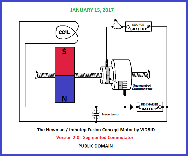
The segmented commutator would send successive fly-back spikes to the re-charge battery per revolution.Code:https://s25.postimg.cc/l3rburwjz/Newman_Imhotep_Fusion_Concept_Motor_by_VIDBID_ve.png
I think J. L. Naudin's Keys would be applicable in the above set-up.Last edited by vidbid; 02-15-2019, 05:30 AM.Leave a comment:
-
Newman Motor Keys by J. L. Naudin
Source: http://jnaudin.free.fr/html/NWMkeys.htm
THE NEWMAN'S MACHINE KEYS FOUNDS on 06-27-98
Key ONE : The FREE energy must be tapped from the collector (inductor) WHILE it charges itself with its own magnetic energy,
Key TWO : HIGHER the POTENTIAL, HIGHER the NEGATIVE POWER tapped.
Key THREE : GREATER THE NUMBER of STEPS (Broken flow) DURING THE CHARGING PHASE of the "collector", GREATER the efficiency.....
Key FOUR : To get more electrical power back from the coil, the pulse duration must be at least 1/20th of the L/R timeconstant and, at the same time, a very big _changing_ magnetic field must be applied (generated by a rotating permanent magnet rotor).
Key FIFTH : The negative current comes from the DISRUPTIVE EFFECT caused by the "Broken segments" or a bumpy surface during the firing sequence. The negative energy (the real Free Energy) is pumped from the vaccuum DURING THE DROPS OF POSITIVE CURRENT. These drops create a kind of "syphon effect" in the Aether which pumps free energy and creates these deep and strong spikes showed in my scope picture.
Key SIX : The duration or the "life" of this negative current can be SUSTAINED by SMALL FLUCTUATIONS in the dropping potential, just after the disruption. This can be done by some SPECIAL SPARK-GAP DESIGN or a SPECIAL SHAPE of the "Broken segments".
more keys coming soon.....
Leave a comment:

Leave a comment: