This forum is preserved as a permanent archive. The community continues at eMedia Press.

Announcement

Collapse
No announcement yet.

Newman Motor Finally Explained?

Collapse
X
 
  • Filter
  • Time
  • Show
Clear All
new posts

  • ilandtan
    replied
    Originally posted by Vinyasi View Post
    The most interesting part is that it matters what the wiring position of the brushes are in relation to the commutator. If they're on the side of the commutator facing the rotor coils, then OverUnity will result. But if the brushes are sparking on the side of the commutator opposite the rotor coils facing the circuit surrounding the D/C motor / alternator, then smooth half sinewaves (similar to a crystal radio audio output) will result and no OverUnity...
    Vinyasi,

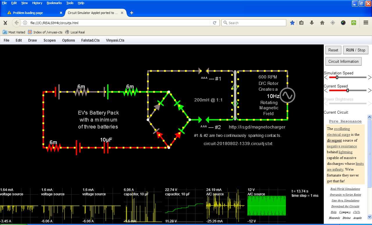
    Could you provide a picture of this so I can visualize the orientation of the sparks in relation to the magnetic field?

    Thanks!
    Leave a comment:


  • vidbid
    replied
    interesting

    [VIDEO]https://www.youtube.com/watch?v=CrJIzrmX1mI[/VIDEO]

    Code:
    https://www.youtube.com/watch?v=CrJIzrmX1mI
    Joseph Newman - YouTube

    interesting

    Leave a comment:


  • Vinyasi
    replied
    Dave Bowling's 3 Battery Generator includes Newman's Unknown Extra Energy Source

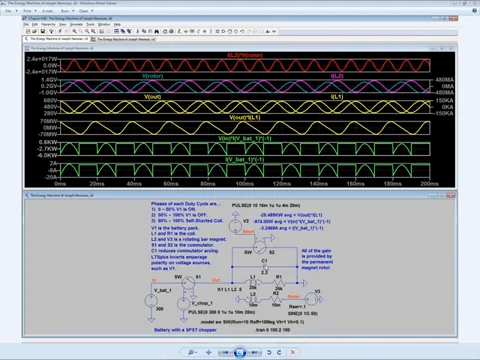
    Ever since I managed to understand Newman's eighth edition enough to simulate it, I've been of the opinion that - although it's overunity - it's not entirely a mystery where the extra energy comes from.

    It comes from the spinning magnetic field surrounding the rotating bar magnet/s in the center of the coil. They produce lots of amps, but not much volts. These sinewaves then blend with the square waves arriving from the battery pack, and then chopped up by the commutator, creating a blended waveform.

    The massive coil is doing more than merely filter out current flowing from the batteries. It also draws current through the rotating magnetic field surrounding the spinning permanent magnets. As to where this excessive current comes from, I don't know...

    But I do know that most of it goes to waste due to the poor coupling coefficient between the spinning magnetic field and the massive coil which surrounds it.

    Well....

    What helped me understand Dave Bowling's Three Battery Generator was the key advice from him and others replicating his work, to: "hand turn the axle of the D/C brush motor after five minutes of waiting for it to self-start if it should fail to". This is exactly like the Newman motor. Thus, I began to attempt a set of simulations...


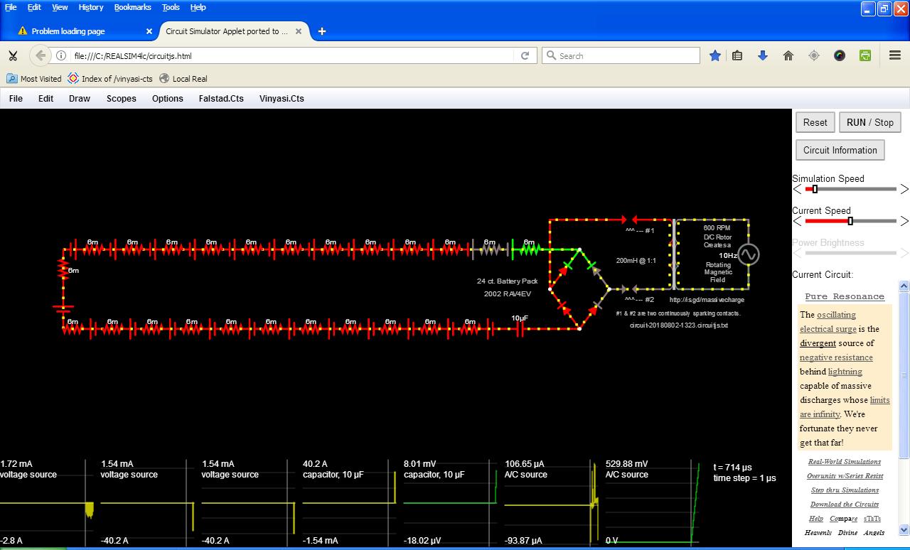
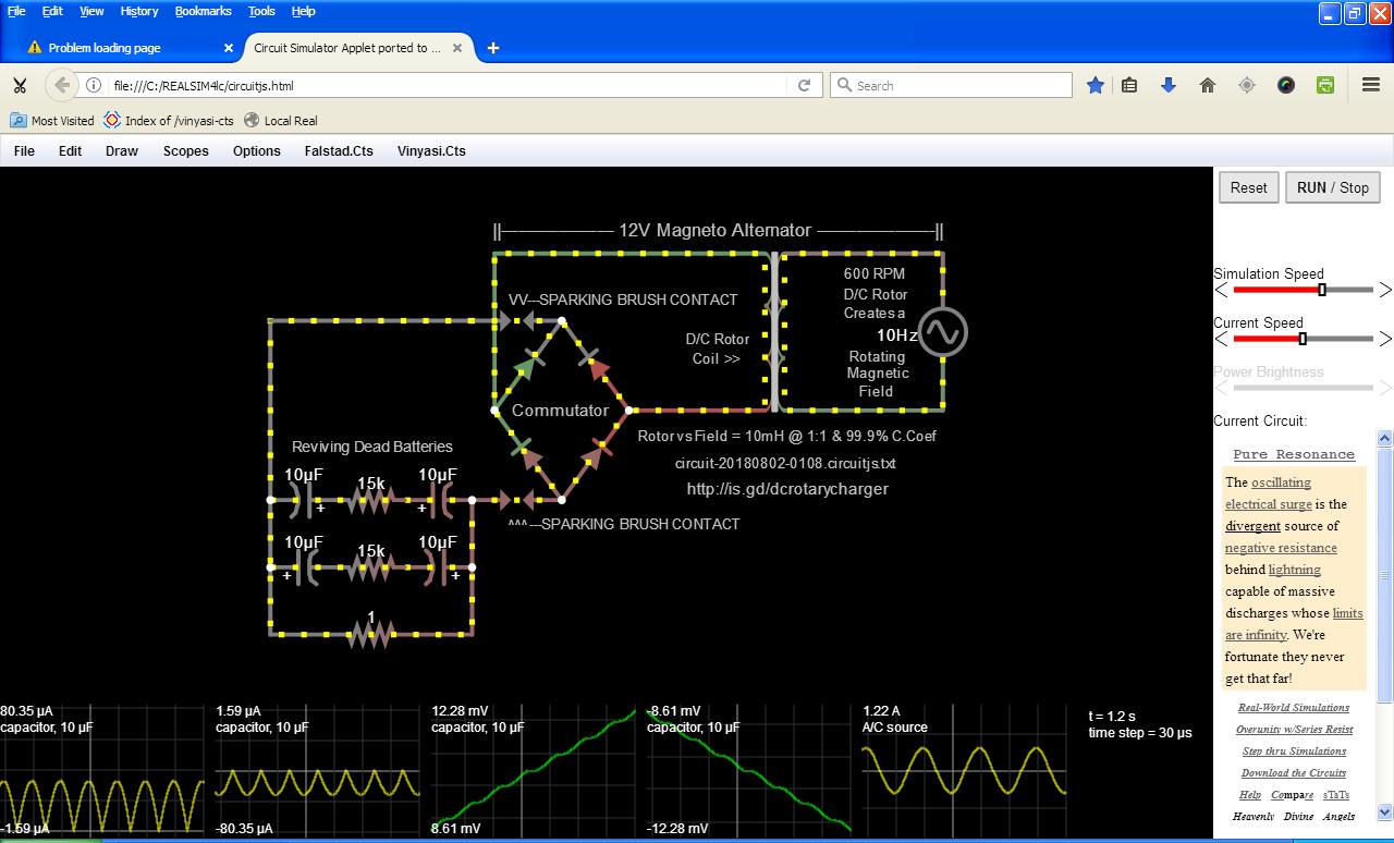
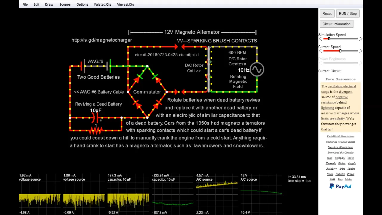
    It's possible to simulate increased current drawn from a source (the sparking brushes in these examples) whenever the load increases (represented by adding more batteries that need charging) along with decreased current at the initial source (the rotating magnetic field of the magneto rotor represented by the A/C voltage source in these simulations) ....


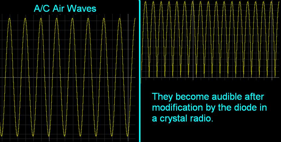
    The most interesting part is that it matters what the wiring position of the brushes are in relation to the commutator. If they're on the side of the commutator facing the rotor coils, then OverUnity will result. But if the brushes are sparking on the side of the commutator opposite the rotor coils facing the circuit surrounding the D/C motor / alternator, then smooth half sinewaves (similar to a crystal radio audio output) will result and no OverUnity...


    More information about these simulations.

    Short animation ...
    Dave Bowling discovered this three battery setup quite by happy accident while testing John Bedini's three battery charging setup. The difference is in the load placed between the positive terminals: a small motor with sparking brush contacts needing a hand crank to start. http://is.gd/magnetocharger http://is.gd/3battgeninfo http://is.gd/battgen http://is.gd/plasmaarc This video ... https://vimeo.com/vinyasi/magnetocharger
    Last edited by Vinyasi; 07-26-2018, 08:49 AM. Reason: UPDATED INFO

    Leave a comment:


  • Vinyasi
    replied
    I like this ...

    Originally posted by Majestic81 View Post
    ... a maximum potential difference to create the magnetic field with minimum input and collapse it with potentially more output.

    Ray
    Succinct and to the point.

    Leave a comment:


  • Majestic81
    replied
    Originally posted by citfta View Post
    WOW WOW WOW

    I am so glad to see you are finally starting to wise up and not believe everything you see on YouTube or hear about from this source or that source. I actually have an original Joseph Newman Energy Machine book from back in the 1980's. I was very intrigued by what he wrote. But then I saw an article where he was actually driving a car powered by one of his motors and some 9 volt batteries. I am sure you are thinking the same thing I thought. He can run a car on 9 volt batteries! That is amazing! Then I found out he was using a couple of thousand of them connected in series and parallel to give him a couple of thousand volts at a few amps. He was just trading volts for amps. Nothing magical or OU about that at all. I was very disappointed in him.

    Now maybe you can understand why those of us that have been at this a while are not so quick to jump on the bandwagon for every guy that comes on YouTube or this forum claiming he's "GOT IT" and then doesn't show any real proof he has anything.

    I most definitely believe OU is possible. But I am very skeptical of those making wild claims when they show nothing to back those claims up. And since I have been at this a while I have seen a lot of the same old stuff shown over and over again that still doesn't work.

    Respectfully,
    Carroll
    Nah, he was creating a maximum potential difference to create the magnetic field with minimum input and collapse it with potentially more output.

    Ray

    Leave a comment:


  • Vinyasi
    replied
    Divide and Conquer the Synthesis of Electrical Watts

    Leave a comment:


  • vidbid
    replied
    Joseph Newman's Motor Doesn't Kill the Dipole of Current vs Voltage. It Maintains it in Perpetuity


    Cooperation will Solve this Mystery of the Newman Motor


    Some of my other favorite video saves about Newman:

    newman motor batteries too dead to run the motor until the capacitor connected
    newman motor batteries too dead to run the motor until the capacitor connected


    I also saved this video (Geoffrey Miller Energy Bat Labs Live Call) available at https://www.youtube.com/watch?v=R8QLWrPpQaM

    Leave a comment:


  • Vinyasi
    replied
    I wasn't going to simulate any further since I'm tired of that ...

    Responding to Vidbid...


    But this loss has prompted me to overwork since I have to repost as many missing videos as my patience can tolerate while inspired to make a few more.

    I have to publicly thank Anthony Craddock for asking whatever happened to a duplicate location of the video you transcribed after having already privately thanking him. Forgetting about the former video, I reuploaded another plus almost all of the videos showcased on ...


    I seem to have misplaced one making analogy between homopolar motors / generators and the Newman device probably since I renamed a few upon posting them. Life goes on...

    Capacitance may Induce Helium to Acquire a Magnetic Field?

    I just got off the phone with Byron in which he assured me that Jo got a boost to his rotating central magnets by using sets of ring magnets surrounding sets of capped PVC pipes (coated with either wax or something similar to prevent getting nasty shocks; I wonder if epoxy would could make do?) acting as canisters containing helium. The magnets supplied an alternating push / pull effect while the helium, being diamagnetic, supplied a repulsive push effect.

    Thanks for your boost. I appreciate it.
    Last edited by Vinyasi; 06-03-2018, 02:25 AM.

    Leave a comment:


  • vidbid
    replied
    Originally posted by Vinyasi View Post
    https://youtu.be/z_nKxuLAcUM

    According to Byron Brubaker, Jo had helium filled inside of those rotating permanent magnets. Apparently, if a glass globe were to be filled with helium and wrapped with a copper winding, then interesting EMs occurs in that winding. This I can't account for in my simulations except that I hint at a second source of energy sourced from these rotations blending with the DC coming from the battery pack.
    Sorry about your channel being removed.

    It was a good channel. I quote you in the following posts:

    http://www.energeticforum.com/307577-post420.html and https://archive.org/details/GettingMoreFromLess


    maintaining a perpetual voltage/amperage dipole

    ..looks like the powers that be are occulting this knowledge

    ..looks like they took down energybat's channel, as well

    here's his stuff : https://www.youtube.com/watch?v=1wh9G1mU9UU


    Now, currently looking at https://www.youtube.com/watch?v=yvI4dQ87Vws and


    Last edited by vidbid; 06-03-2018, 01:37 PM.

    Leave a comment:


  • Vinyasi
    replied
    I don't know who Richard Willis is, but...

    Originally posted by boguslaw View Post
    Sorry, I'm not on track with this topic but my intuition tells me that Newman machine is just a bigger version of Richard Willis first prototype (or rather Richard Willis incidentally constructed his first prototype in fashion similar to Newman machine). Try to find photos and compare, you will have very big help for successfully building Newman generator.
    According to Byron Brubaker, Jo had helium filled inside of those rotating permanent magnets. Apparently, if a glass globe were to be filled with helium and wrapped with a copper winding, then interesting EMs occurs in that winding. This I can't account for in my simulations except that I hint at a second source of energy sourced from these rotations blending with the DC coming from the battery pack.

    Leave a comment:


  • Vinyasi
    replied
    It's a good thing you did this since my YouTube channel has been removed...

    Originally posted by vidbid View Post
    Part 3

    Okay, this is Part 3. Enjoy.


    According to Byron Brubaker, Jo had helium filled inside of those rotating permanent magnets. Apparently, if a glass globe were to be filled with helium and wrapped with a copper winding, then interesting EMs occurs in that winding. This I can't account for in my simulations except that I hint at a second source of energy sourced from these rotations blending with the DC coming from the battery pack.

    Leave a comment:


  • wantomake
    replied
    Image

    Thanks Vidbid,
    This is best guide to build from. I only built the smaller version so it wasn't much help to me. But I did get some understanding from it. Would been great to see the EV car size J. Newman built. Or how he built it to size.

    Clarence is building a good looking table top version. Happy building ole friend.

    Wantomake

    Leave a comment:


  • vidbid
    replied
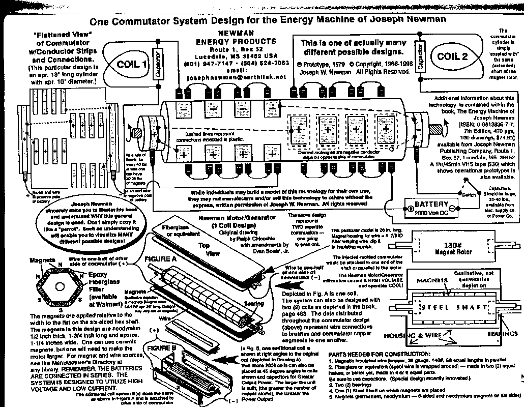
    Reposting Missing Image


    I had posted this image before, but website postimg.org made some changes to their domain, so I had to go back and find the missing image and post it here.
    Attached Files
    Last edited by vidbid; 05-27-2018, 05:40 AM.

    Leave a comment:


  • wantomake
    replied
    Good uses

    Clarence ole friend,
    I understand about the funds. The SS doesn't go so far these days.

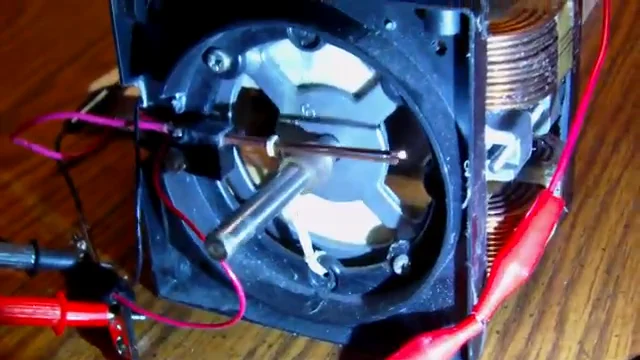
    The second commutator will do the job timing the on,off, and shorting to the capacitor. From the picture you posted I built a short and smaller version. It was 2" pvc pipe with caps on ends that held it in place on threaded rod. Used 1/2" copper strips from old started coils. But as the picture shows more contact area keeps the sparking down to avoid heat and scarring of the contacts.

    Look forward to your progress. We got big time monsoon season here so just trying to stay dry.

    Later my friend,
    wantomake

    Leave a comment:


  • clarence
    replied
    Change in commutator system

    Originally posted by wantomake View Post
    Brodude,
    Yes over on Small Experiments thread Admin warned him about the disrespect toward another member.

    We All are here to build, learn, support these different builds. Sure there will be those that disagree. But don't be disruptive and negative. Show your work with explanation and in the "spirit" of FE exploration.

    Can't wait to see what my ole' sippin friend turns out on his impressive build. We will know with experience and true testing IF indeed J. Newman was a con or genius. Judging from how big brother teamed up against him from the video, I'm thinking the latter.

    Just my opinion.
    As always time to nuke the coffee,
    wantomake
    Hello wantomake,


    Since last word from me,
    I found out that I DO need a DUAL Commutator system to ALTERNATE the DC
    voltage through the coil.
    The DUAL commutator will allow enough Fire time to off time through the coil
    To get the job done.
    Only problem is that another commutator and brush holder will have to be purchased .
    At present my funds to do so are just not there. More will not be available until June 20 th.
    Means a real long wait. So nothing will be coming from me during that time.

    Just wanted to let you and members know.

    Respectively,

    Clarence
    Attached Files

    Leave a comment:

Working...
X