This forum is preserved as a permanent archive. The community continues at eMedia Press.

Announcement

Collapse
No announcement yet.

Newman Motor Finally Explained?

Collapse
X
 
  • Filter
  • Time
  • Show
Clear All
new posts

  • Model 15-C2 or 22-K1

    So, to continue, I have plans to build the unit that was tested by Dr. Roger Hastings, described in detail in Chapter 6 of Newman's book.
    This one isn't that big (145 lbs.) and according to the specs produced 10 Watts of output with an input of less than 0.5 Watt.

    See attached picture.
    Has anybody replicated this unit, and what were his/her findings?

    I want this model on my test bench, and when it's there I plan to build a second better version with some of the components replaced by electronic parts, to improve the overall working of the device and get more out of it.

    To be clear on the subject, I have no intend to build a big one with lots of pounds of copper in it. Too expensive for me. Although that has proved to be one great working model, if I understand correctly the theory explained in the book by Newman himself, there should not be a need to do so. Nevertheless I need something to start with, and I think the small unit of Chapter 6 is an excellent starting point.

    pjotterkjen
    Attached Files

    Comment


    • Originally posted by pjotterkjen View Post
      So, to continue, I have plans to build the unit that was tested by Dr. Roger Hastings, described in detail in Chapter 6 of Newman's book.
      Thanks for that.

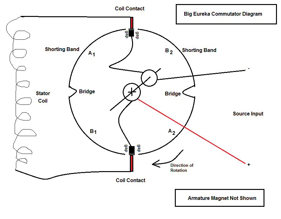
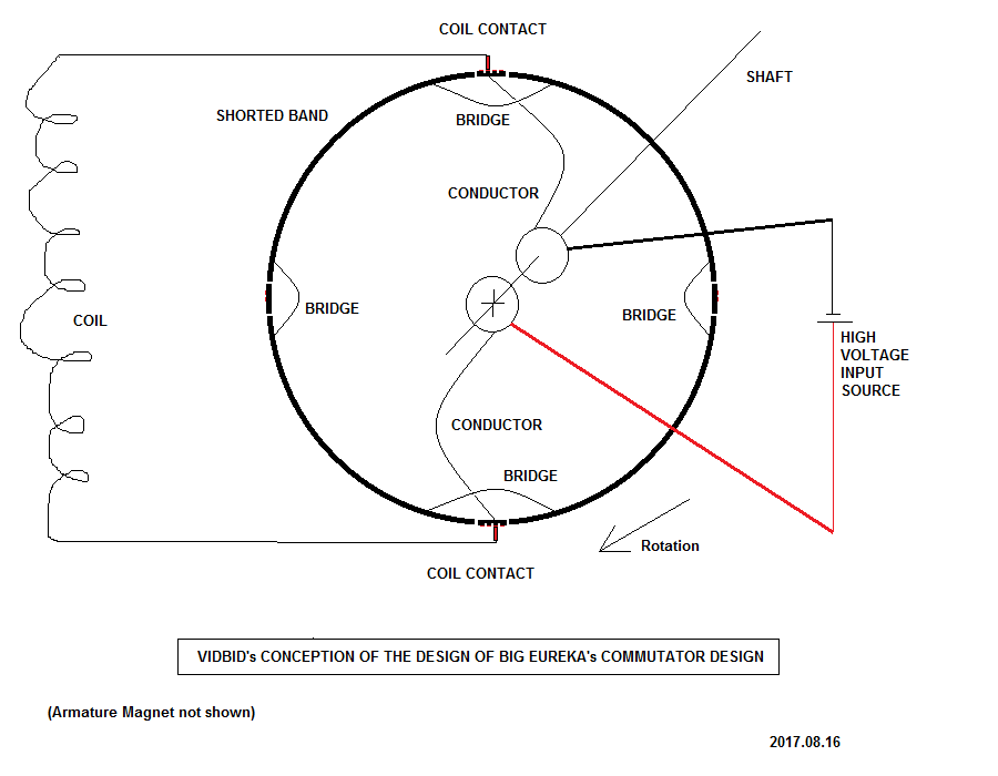
      Below is my diagram of Newman's recent design..


      While the shorting bands are in contact with the coil contacts, would the coil remain charged?
      Regards,

      VIDBID

      Comment


      • New Diagram

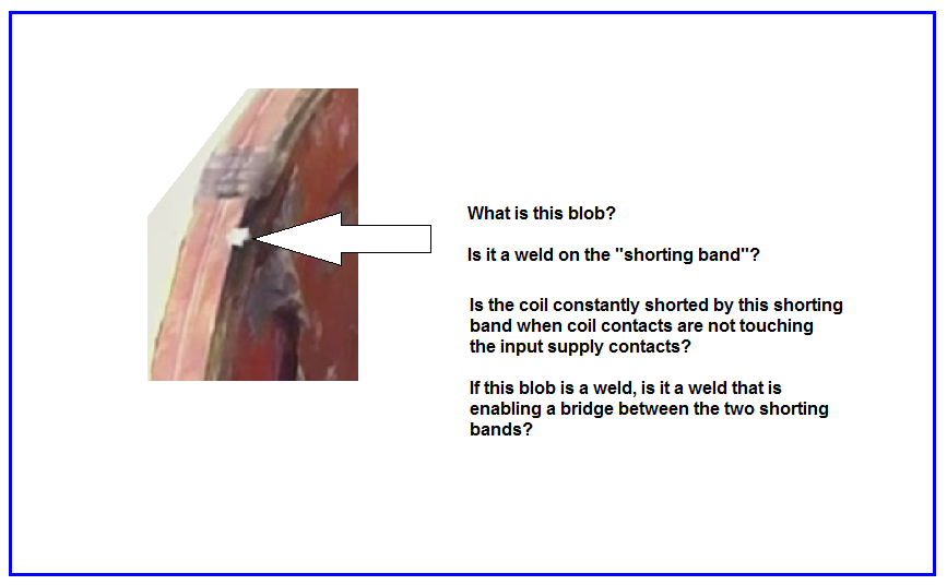
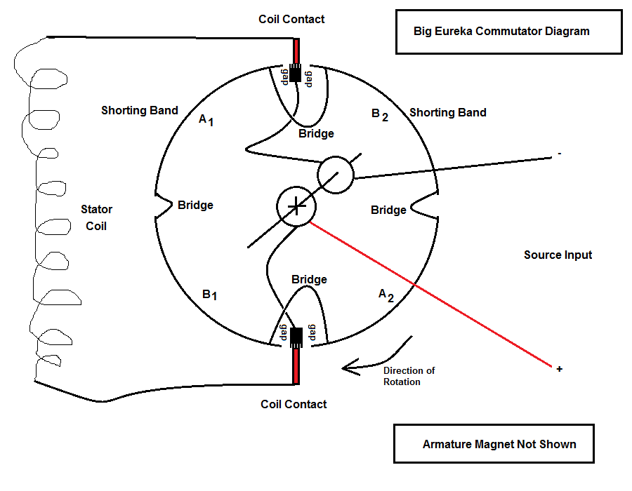
        Noticing a possible weld.

        Maybe the shorting band is continuous.


        Hence, a new diagram with a bridge bypassing the source contacts.

        Last edited by vidbid; 02-15-2019, 05:34 AM.
        Regards,

        VIDBID

        Comment


        • Originally posted by vidbid View Post
          Thanks for that.

          Below is my diagram of Newman's recent design..


          While the shorting bands are in contact with the coil contacts, would the coil remain charged?
          I think the coil is not directly connected.

          The inner ring connections look OK to me.

          Based on what I saw in the video so far, the only thing I'm pretty sure of is that the commutator on the outer ring sparks twice each revolution (I earlier thought it was only one time, my fault). Advancing the video a bit, we see the upper brush also sparks twice per revolution. But these upper sparks seem to be somewhat less bright.

          So to further reason, if the outer ring has only two long copper strips separated by two gaps (and no bridges), then they still do not represent the FIRE, BLANK, and SHORT segments, which we know are required in this machine to create an excess of electromagnetic energy in the coil copper atoms, as the input voltage pressure generates that as only being the 'catalytic' effect. The coil should be hit with a hammer repeatedly, or as Newman stated more like short strong punches like in boxing.

          I'm convinced these three important segments and their critical timing are being handled inside the big cover-up.

          pjotterkjen

          Comment


          • Missing image in the previous post:


            ----------------------------------------------------------

            Originally posted by vidbid View Post
            Noticing a possible weld.

            Maybe the shorting band is continuous.


            Hence, a new diagram with a bridge bypassing the source contacts.


            This is the design that I going with presently.
            Last edited by vidbid; 02-15-2019, 05:36 AM.
            Regards,

            VIDBID

            Comment


            • Latest Design


              I believe that the result of the above design is that the coil remains shorted whenever it is not being charged by the battery.
              Last edited by vidbid; 02-15-2019, 05:37 AM.
              Regards,

              VIDBID

              Comment


              • Comment


                • No Claim Made As To Coil Constatly Being Shorted

                  Originally posted by pjotterkjen View Post
                  @vidbid: Would you mind explaining how this motor would start running on itself as was shown in the documentary, when the commutator was constantly shorting the coil?
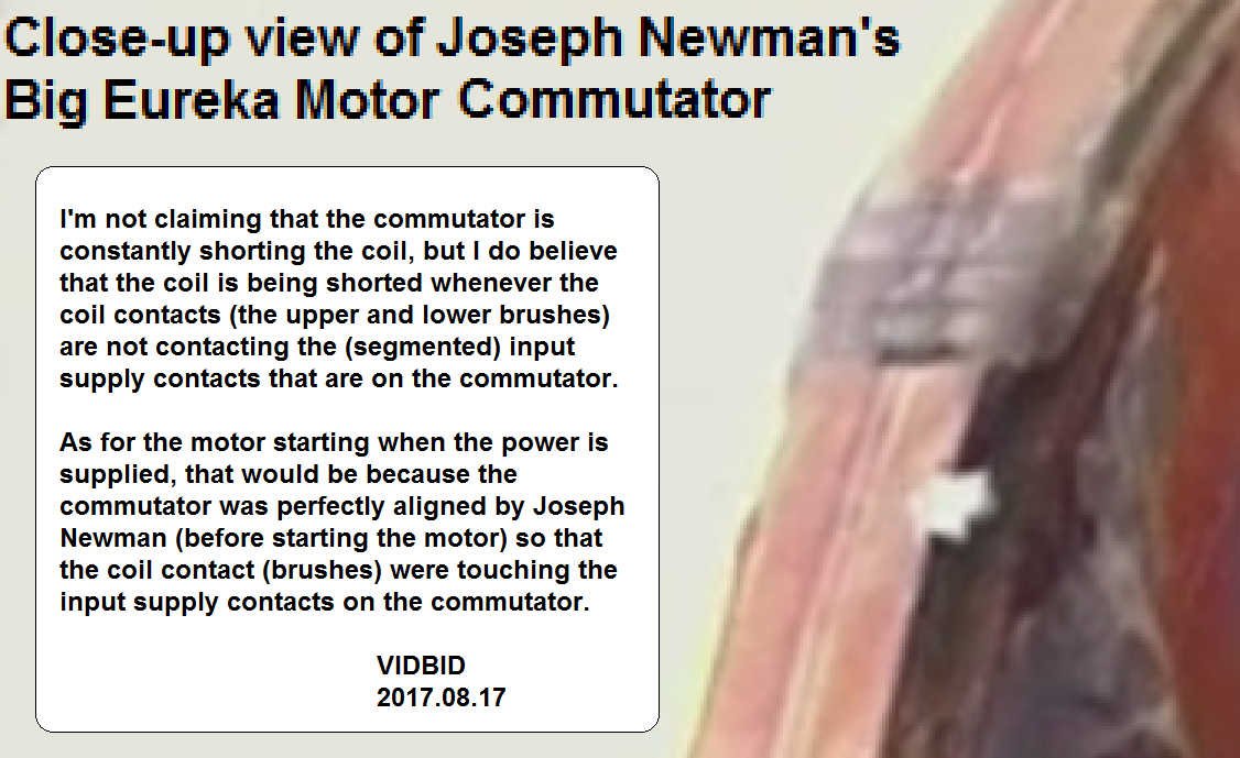
                  Please refer to the posted image for my response:

                  Last edited by vidbid; 02-15-2019, 05:38 AM.
                  Regards,

                  VIDBID

                  Comment


                  • Postimg.org for image hosting

                    Originally posted by pjotterkjen View Post
                    I do not have space anymore to attach more images, otherwise I'd attach a picture of it.
                    I use postimg.org to host my images free-of-charge; you can use their service without even signing up:


                    https://postimages.org/

                    .
                    .
                    .

                    Later note: I don't recommend them anymore.
                    Last edited by vidbid; 02-15-2019, 05:38 AM.
                    Regards,

                    VIDBID

                    Comment


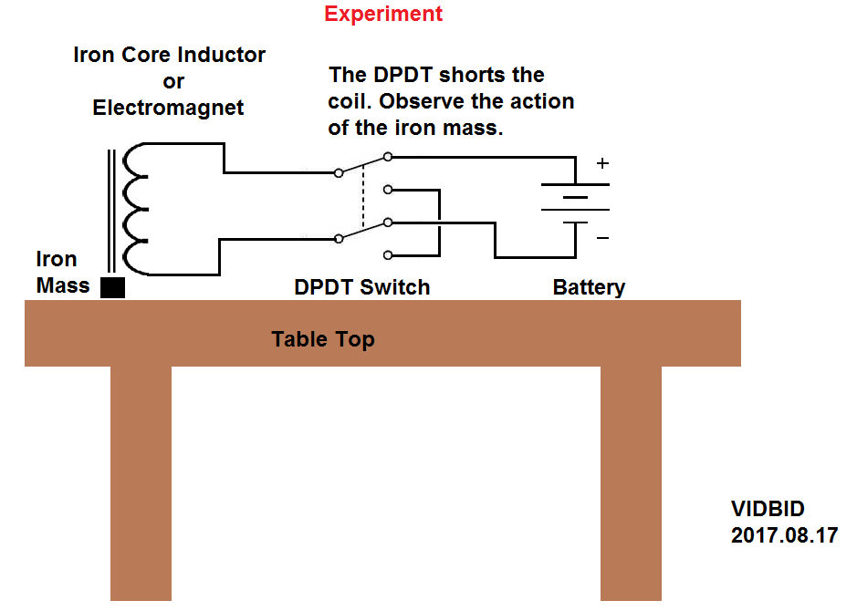
                    • Experiment


                      Check out this experiment.
                      Last edited by vidbid; 02-15-2019, 05:39 AM.
                      Regards,

                      VIDBID

                      Comment


                      • Originally posted by vidbid View Post
                        I use postimg.org to host my images free-of-charge; you can use their service without even signing up:


                        https://postimages.org/

                        .
                        .
                        .
                        Hey nice of you, thanks!

                        Comment


                        • Originally posted by vidbid View Post
                          Please refer to the posted image for my response:

                          OK, now I see your point. You think the coil is shorted when passing over the two gaps. Let's assume that is the case. Somehow the coil must get blanked (here, blanking means disconnecting the input voltage from the batteries) and shorted in those two little gaps. Twice per revolution.

                          Exactly where is that done, and how the sparks caused by the back EMF is handled, is still open to discussion, of course.

                          I'll be commenting on some interesting things related to the commutator I've seen in the videos, later on.

                          pjotterkjen

                          Comment


                          • Last edited by pjotterkjen; 08-19-2017, 01:16 AM. Reason: correcting image URLs

                            Comment


                            • @pjotterkjen

                              To my knowledge, there isn't any evidence to support the position of there being a hidden commutator.

                              With that being said, I'm aware of Big Eureka's precursor and its corresponding commutator. The reason for its design is to increase the resistance of the commutator contact gaps, but as Geoffrey Miller stated, to the effect, that once Newman achieved what he was looking for, he stopped making enhancements.

                              I believe that no one can dispute that Big Eureka was the final version, and for that reason, I think it makes sense to study it. Thank you for the images of the spark discharge coming off of the coil contacts, but you'll notice if you watch his videos of Big Eureka, while facing the front of the motor, the commutator revolves in a clockwise direction. I believe the spark discharge is the fly-back discharge coming off of the coil, but that would have stopped once the coil brushes would have contacted the shorting band, probably allowing the magnetic field in the stator coil to remain charged, thereby keeping its magnetic field mostly intact.

                              That's just my opinion. The only way to test my theory is to build a prototype motor with my design or what I believe Newman's final design to be or to build the above experiment in my previous post.
                              Last edited by vidbid; 08-19-2017, 04:12 AM.
                              Regards,

                              VIDBID

                              Comment


                              • Originally posted by vidbid View Post
                                @pjotterkjen
                                The only way to test my theory is to build a prototype motor with my design or what I believe Newman's final design to be or to build the above experiment in my previous post.
                                OK, let us know when you have the device on your bench and please share the test results!

                                pjotterkjen

                                Comment

                                Working...
                                X