
 Tweet
Tweet
Hy everybody.
There's a simply but in my opinion as far as I have seek, unanswered question regarding the theoretical resonance in a Tesla Coil.
We use to calculate in using the theoretical formulas stated by Eric Dollard (I think it will not be necessary to repeat them here). For example, in the Lakhosvky Multiple Wave Circuit, we think that the resonance is the one regarding the third part of the circuit (which is the most important one), where's the secondary step-up transformer. As we can see in the next diagram;
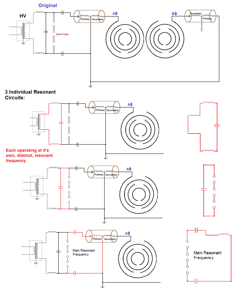
The resonance of the full circuit will be something related to the second Oudin/Tesla Step Up Transformer, considering resistance negligible;
C1L1 = C2L2
where C1 is the equivalent capacitance of the first two capacitors, L1 the inductance of the primary coil, C2 the capacitance of the rings of the antennas (typically some pF of the ball or Toroid used in common Tesla Coils) and L2 the inductance of the secondary coil.
But after the electricity passes though a spark gap, there's no electrical frequency in the circuit instead of a Multiple Frequencies, and most of this range of frequencies depend more in the spark gap distance rather than the inductances and capacitances of the circuit, which can create more high frequencies depending on the distance of the gap. A part, we know that the inductance of a coil that you measure using a inductance meter will no longer be the same one when the circuit is running. So...
Will be necessary or even mandatory to calculate the resonance of a Oudin Coil using this ancient method describe in this video, passing a foil over the bare wire of a naked Oudin Coil ?
I will be looking forward to read your answers.
From Spain, thanks.
There's a simply but in my opinion as far as I have seek, unanswered question regarding the theoretical resonance in a Tesla Coil.
We use to calculate in using the theoretical formulas stated by Eric Dollard (I think it will not be necessary to repeat them here). For example, in the Lakhosvky Multiple Wave Circuit, we think that the resonance is the one regarding the third part of the circuit (which is the most important one), where's the secondary step-up transformer. As we can see in the next diagram;
The resonance of the full circuit will be something related to the second Oudin/Tesla Step Up Transformer, considering resistance negligible;
C1L1 = C2L2
where C1 is the equivalent capacitance of the first two capacitors, L1 the inductance of the primary coil, C2 the capacitance of the rings of the antennas (typically some pF of the ball or Toroid used in common Tesla Coils) and L2 the inductance of the secondary coil.
But after the electricity passes though a spark gap, there's no electrical frequency in the circuit instead of a Multiple Frequencies, and most of this range of frequencies depend more in the spark gap distance rather than the inductances and capacitances of the circuit, which can create more high frequencies depending on the distance of the gap. A part, we know that the inductance of a coil that you measure using a inductance meter will no longer be the same one when the circuit is running. So...
Will be necessary or even mandatory to calculate the resonance of a Oudin Coil using this ancient method describe in this video, passing a foil over the bare wire of a naked Oudin Coil ?
I will be looking forward to read your answers.
From Spain, thanks.

Comment