Announcement

Collapse
No announcement yet.

Re-Inventing The Wheel-Part1-Clemente_Figuera

Collapse
X
 
  • Filter
  • Time
  • Show
Clear All
new posts

  • Originally posted by Listener192 View Post
    Hi UFO,

    Well its about 50W average output for 300W DC input. Those current waveforms have some phase shift and do not cancel, so a loose coupled transformer action is occuring, somewhere in the order of 5A Pk-Pk out of 20A Pk-Pk swing.

    A minimal change in input current when shorting both output coils does really prove anything if it is operating as a loose coupled transformer.

    I could make scope power measurements and post them but they are not even in the ball park.

    I have tried shifting the sine in code, also reducing the modulated amplitude. the distortions remain although operating into a resistive load produces a perfect current sine.

    I have also tried twin single ended MOSFET switches but that needs a flyback diode and the distortion is worse. Possibly a PWM system with a feedback correctional loop would produce a clean sine.

    Anyway... still thinking about it.

    L192
    Got You, Thanks, Listener192,

    Ok, but you must realize Your Coil-Core size ratio of your secondary versus your two primaries...I would say the Sec Length is about 1/3rd off One of your Primaries...

    However, Generally speaking, Your results are EXACTLY what I have explained to Netica on the other Thread...this set up (NOT meaning yours, but related to Figuera Patent Main Design, BASICALLY of Primary-Secondaries alignment and positioning) will NOT DO IT, meaning going OU.

    Your two sines are almost perfect...

    Thanks for sharing it!!


    Regards


    Ufopolitics
    Principles for the Development of a Complete Mind: Study the science of art. Study the art of science. Develop your senses- especially learn how to see. Realize that everything connects to everything else.― Leonardo da Vinci

    Comment


    • Load I & V single and twin primaries

      Hi UFO,

      Attached are scope shots of Load current (yellow) and voltage (blue)

      Single primary and twin primaries.

      Probe is a differential type on x 50. Scaling setting to read actual volts.

      L192
      Attached Files

      Comment


      • PWM Class D single rail amplifier

        I think that the attached Class D amplifier arrangement may provide the solution to a symmetrical sine. A commercial single rail D class amplifier could be used, just leave out the output capacitor that normally provides the DC isolation.

        Perhaps a cheap medium power amplifier with upgraded MOSFETs or even paralleled MOSFETs.

        One you would be feed with a zero degree sine and the other a 10 degree sine.
        Phase corrections could be easily applied to the sines to achieve perfect cancellation.

        L192
        Attached Files

        Comment


        • but it reduced its output whenever I added another positive switching to a second primary with a common ground (typical Figuera way)...And these testing results made me move into this new form of switching.


          The question to all Electronic developers here, like El Cheapo or Listener192...
          Last edited by Ufopolitics; 08-16-2017, 03:28 PM.
          Principles for the Development of a Complete Mind: Study the science of art. Study the art of science. Develop your senses- especially learn how to see. Realize that everything connects to everything else.― Leonardo da Vinci

          Comment


          • The Switch Contacts and Rotating Brushes...

            Hello to All,

            In order to have a more solid, real idea...

            This is the Mechanical Way, I am achieving the previous Signal...:


            I have TWO CENTER OFFSET ROTATING BRUSHES shown, which are NOT Connected to absolutely nothingexact deal as we get in a Symmetrical Brushed Motor...where BEMF is controlling by Current being back-forward directed alternatively.
            Last edited by Ufopolitics; 08-16-2017, 07:14 PM.
            Principles for the Development of a Complete Mind: Study the science of art. Study the art of science. Develop your senses- especially learn how to see. Realize that everything connects to everything else.― Leonardo da Vinci

            Comment


            • D class amplifier

              It took a little time but I have one D class amp built. Its based on the NCP5106 Dual MOSFET driver, which allows the use on N channel devices.
              It also provides the shoot through prevention. I am using 2 x 600V 53A MOSFET's. This driver is one I gave up on several years ago as MOSFET failure takes the driver out every time. In this case the application is fairly benign.

              This one takes its PWM from the arduino, after TTL to CMOS 15V signal conversion.

              I did some testing with square waves (no PWM) and it seems to drive a coil OK at 20A Pk-Pk.

              Once have a PWM sine feeding it I will see what the sine current distortion is like.

              Of course it could be driven with a PWM square wave, that would just control the amplitude of the square wave.

              L192

              Comment


              • New Switching Waveform

                Originally posted by Ufopolitics View Post
                but it reduced its output whenever I added another positive switching to a second primary with a common ground (typical Figuera way)...And these testing results made me move into this new form of switching.


                The question to all Electronic developers here, like El Cheapo or Listener192...
                Hi UFO,

                Yes you could generate this waveform with an H bridge, just like a sine inverter with a + & - rail, except in this case you delay before switching the polarity via the second set of transistors in the bridge.

                L192

                Comment


                • Trailing edge dimmer

                  Hi UFO,

                  As you are now generating AC, a simpler option may be to use a trailing edge dimmer, see attached.

                  If you try to generate a square current waveform, now you are using AC on the coil, complete magnetic reset and reversal will mean that the full inductance of the coil will be seen, unlike the DC method. Your current wave shape will be closer to a sawtooth.

                  With a trailing edge dimmer, the leading edge will be a sine and your 135/45 degree waveform could be easily set. A variable tap transformer or variac could be used with the dimmer to control current amplitude.

                  The only reason for using PWM, would be if you wanted to control the current amplitude while generating the square waveform from +& - DC rails.

                  L192
                  Attached Files

                  Comment


                  • Originally posted by Listener192 View Post
                    Hi UFO,

                    As you are now generating AC, a simpler option may be to use a trailing edge dimmer, see attached.

                    If you try to generate a square current waveform, now you are using AC on the coil, complete magnetic reset and reversal will mean that the full inductance of the coil will be seen, unlike the DC method. Your current wave shape will be closer to a sawtooth.

                    With a trailing edge dimmer, the leading edge will be a sine and your 135/45 degree waveform could be easily set. A variable tap transformer or variac could be used with the dimmer to control current amplitude.

                    The only reason for using PWM, would be if you wanted to control the current amplitude while generating the square waveform from +& - DC rails.

                    L192
                    Thanks Listener192,

                    I have seen, and own some Three Phase BLDC Motor Controllers...which I know work based on an "H Bridge", however this is a Basic Single Phase Signal (so far).

                    You are right I have now an AC Signal, BUT, remember it is generated by DC, and so please note the Flat Line On Times
                    Last edited by Ufopolitics; 08-17-2017, 12:49 PM.
                    Principles for the Development of a Complete Mind: Study the science of art. Study the art of science. Develop your senses- especially learn how to see. Realize that everything connects to everything else.― Leonardo da Vinci

                    Comment


                    • D class Amplifier with PWM sine input

                      Attached are some scope shots, showing the results of a resistive load and an inductive load.

                      As you can the sine current is pretty good in both cases however there is a 10A offset in coil current. I need to think on this problem.

                      Experimenting with a UPS filter took out one of my MOSFET's, my mistake as it effectively shorted the 31KHz pulses. I may have got away with this but I only had a temporary heatsink attached to the MOSFET mount rail, so I think they just cooked.

                      So now need to get replacements.
                      L192
                      Attached Files

                      Comment


                      • The Rise of Output Amperage...above Source.

                        Hello Listener192 and All,

                        The Figuera's Signal, which was actually assumed, based on the Interactions from the Patent Images, based on its graphics with commutator and Resistors...does NOT offers a Strong Induction on Secondaries which could render a Higher Amperage which would be ABOVE Input Amperage.

                        Remember Figuera cited this Diagram with Comm and Resistors as an EXAMPLE for the Patenting purposes. And it DOES Generates an Induction on Secondaries...but...

                        ...ONLY with an ABRUPT and RADICAL, Constant Magnetic Field Spiral Reversals, EFFECTED from Exciter to Secondaries Coils, will definitively "PUMP" a MUCH Higher Amperage than what we are Inputting through our Source.


                        You can or can not believe me, or you could keep trying with the Original Assumed Signal...it is up to you...however, time will tell the final answer...


                        Regards to All


                        Ufopolitics
                        Last edited by Ufopolitics; 08-17-2017, 03:04 PM.
                        Principles for the Development of a Complete Mind: Study the science of art. Study the art of science. Develop your senses- especially learn how to see. Realize that everything connects to everything else.― Leonardo da Vinci

                        Comment


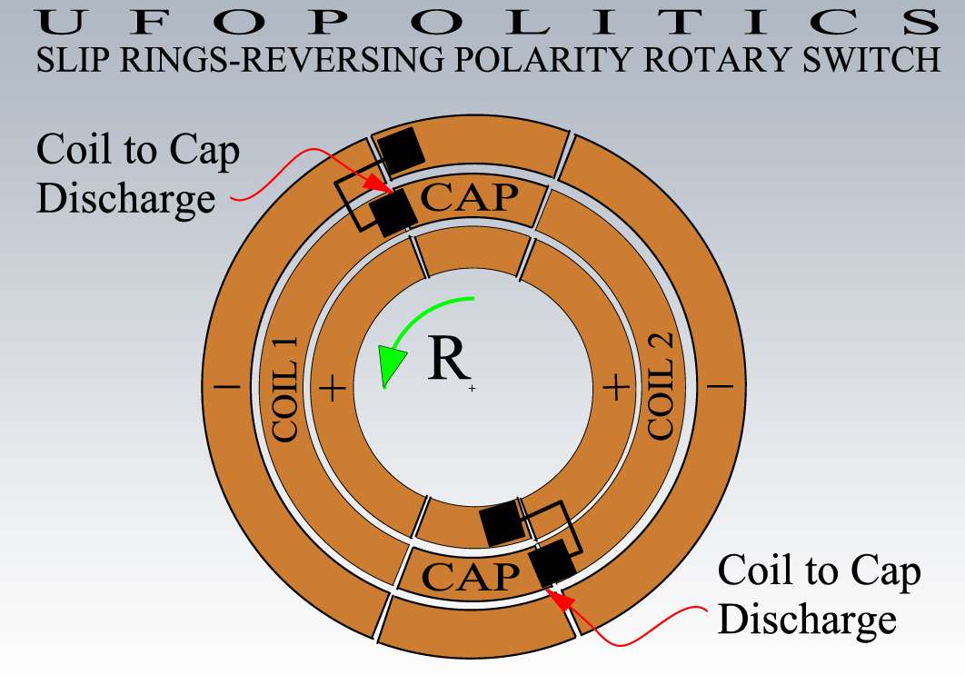
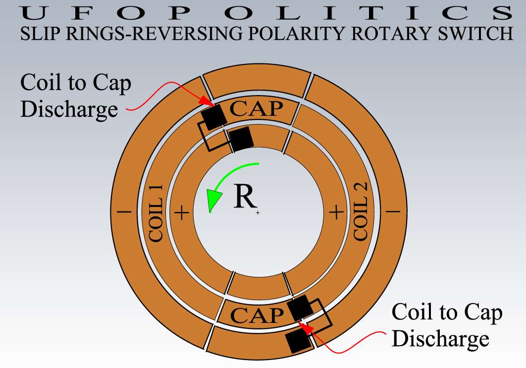
                        • Coil to Cap Discharge Momentum...

                          Hello to All,

                          Below is a better view of the way brushes are positioned related to Slip Arc Segments, as I am showing BOTH Discharge Times in One Cycle from Coil to Cap


                          And...


                          Note that supply brushes are Off from supply arc, by the time Coil Brush is discharging to AC Cap on both positions...


                          Ufopolitics
                          Principles for the Development of a Complete Mind: Study the science of art. Study the art of science. Develop your senses- especially learn how to see. Realize that everything connects to everything else.― Leonardo da Vinci

                          Comment


                          • New Signal

                            Hi UFO,

                            My efforts so far are just to verify that the balanced sine current waveforms cancel flux linking, leaving only the flux cutting component.

                            I have doubts that this will be the case but in deference to the project I thought I would give it the benefit of the doubt.

                            With your new waveform is this applied to two exciter coils N-N in antiphase, or just to a single exciter coil?

                            You mention recovery to a capacitor, could you show a schematic of your setup?

                            Thanks

                            L192

                            Comment


                            • Originally posted by Listener192 View Post
                              Hi UFO,

                              With your new waveform is this applied to two exciter coils N-N in antiphase, or just to a single exciter coil?

                              You mention recovery to a capacitor, could you show a schematic of your setup?

                              Thanks

                              L192
                              Last edited by Ufopolitics; 08-17-2017, 07:24 PM.
                              Principles for the Development of a Complete Mind: Study the science of art. Study the art of science. Develop your senses- especially learn how to see. Realize that everything connects to everything else.― Leonardo da Vinci

                              Comment


                              • Originally posted by Listener192 View Post
                                Hi UFO,

                                My efforts so far are just to verify that the balanced sine current waveforms cancel flux linking, leaving only the flux cutting component.

                                I have doubts that this will be the case but in deference to the project I thought I would give it the benefit of the doubt.

                                L192
                                But you could've check that by making Two Air Gaps between Three Separate Cores, separated by whatever thin insulation...no more " flux linking" there...right?

                                It would still Induce friend...it's called "Spatial Induction"...


                                Regards


                                Ufopolitics
                                Last edited by Ufopolitics; 08-17-2017, 09:27 PM.
                                Principles for the Development of a Complete Mind: Study the science of art. Study the art of science. Develop your senses- especially learn how to see. Realize that everything connects to everything else.― Leonardo da Vinci

                                Comment

                                Working...
                                X