
 Tweet
Tweet
IN THE DESCRIPTIONrectangles N and SIN THE CLAIMS
-
Sorry about this facts, Hanon1492...
Originally posted by hanon1492 View Post
Hello Hanon,
I have done extensive testing on both of this patents (Figuera, Hogan and Jakovlewich), related to dynamic (moving) Generators according to their descriptions...meaning basically rotating HOLLOW, EMPTY copper coils within magnetic fields, just as core the plastics, fiberglass and other insulating-structural materials that hold wiring together...and am very sorry to say this...but it does NOT work.
I was very excited to try this set up in the beginning, but unfortunately, none of the Induced Energy achieved was strong/robust enough, as it occurs when Copper Windings are turned around a laminated or solid steel core...And I do not mean there is no induction at all...there is...but it is minimal and very low amperage carrier electricity is produced...very weak.
I kept researching on this...and I have got many good results with a completely different approach, I will be posting soon.
I started posting Diagrams and Explanations related to this matter, on my Faraday Thread ...take a look at the final two posts...and I will continue tomorrow...
Related to this Spanish Patents, there may be something they are not mentioning, just because that particular revelation would make the patent "too specific" and "Not that General"...so Lawyers inform them NOT TO DO those specifications, as He would not be able to offer any legal protection...this is the main issue with patents...they do not content all data we need to build the devices.
Again, sorry about this my friend...but it is the plain and simple truth based on facts obtained through real testings.
Regards
UfopoliticsPrinciples for the Development of a Complete Mind: Study the science of art. Study the art of science. Develop your senses- especially learn how to see. Realize that everything connects to everything else.― Leonardo da VinciComment
-
Hi Ufo,
Could you please post an sketch or photo of your setup? The esence of Figuera and Hogan and Jakovlewich is create induction between TWO inducers. That is the feature in common, and also in common with some homopolar generator as the N Machine and others. The fact about hollow coils IMHO is not the common key in those patents. We all have done experiments with a simple hollow coil and a magnet and of course here there is nothing special. I will post a no bemf motor link also based on TWO inducers working to compensate the Lenz Law using opposed flux paths to balance this effect. By now just a very interesting video link I have at hand: http://m.youtube.com/watch?v=PTykNjDD0CM
What I mean is that I would like to see your setup to see if that test is really representing the common denominator in all those devices. You can not do some tests, tell that this does not work and keep your data for yourself. In 1902 this generator produced 15 HP and as Figuera was not using all that power he was lighting for free the streets around his house. I guess it worked fine for Figuera.
About current Faraday equation, emf = d(Flux)/dt, I think that it is not complete and it do not grasp all induction phenomena. I am also reasearching about what is behind magnetism ans induction.
RegardsComment
-
I will do...
Originally posted by hanon1492 View PostThat was Nikola Tesla 1888...Coils are enclosed/rotate between Four Stator Fields, not Two...and disposed different than typical Motors-Generators, PLUS, if you could notice the type of Winding is DIAMETRICAL, not RADIAL like also all typical types we know off.The invention is applicable to generators and motors generally, not only to those which I have described in former patents, and which have independent circuits adapted for use in my patented alternating current system, but to other continuous or alternating current machines, such as have heretofore been more generally used.
[IMG]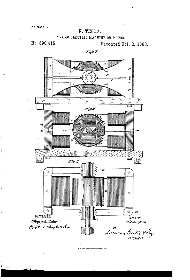 [/IMG]
This was a quick pick patent I chose randomly...but there are many, many that have coils running between two magnetic fields in very similar dispositions.
What I find as a very different approach in those two patents is the fact to use CORE-LESS COILS...not with steel-iron within.
For example, in Figuera's Patent...if He turns those coils in a solid rotor drum attached to shaft...it would be impossible to "Insert" and "Inner Exciter"...it MUST BE Hollow in order to do that.
Again, I did not said they do not work at all...they will induce...but NOT AS MUCH AS if they would have an Iron Core.
There is no need to get upset, We are only searching for the truth by Real Tests.
Related to Luc Video...yes, that is obvious...he is short circuiting coils, like loading them, however, when he turned face to face coils and felt no opposition...that simply means both coils are canceling internally within their spatial volume...he may have some voltage out...as a residual from both forces...by the way...that video was from 2009...did he ever built that generator, based on those principles?
Take it easy friend!...cheers
UfopoliticsLast edited by Ufopolitics; 08-25-2014, 10:13 PM.Principles for the Development of a Complete Mind: Study the science of art. Study the art of science. Develop your senses- especially learn how to see. Realize that everything connects to everything else.― Leonardo da VinciComment
-
drum is never solind inside
Comment
-
TWO INDUCTORSpatent 30376 and patent 30378) and the machine from 1908 (patent 44267) all are based on placing two lateral inductors and one central induced circuit.
With this premise, I may guess that Figuera was trying to get an special effect by the use of two inductors. For me this is the common principle which underlies in all his patents.
If it was not the case then Figuera could have designed his machines with just one inductor and one induced. As a first approach we may think that the use of two inductors could be related to:
1- As we have discussed previously, maybe in the 1908 patent Figuera was placing both inductors with like poles facing each other (N-N or S-S) in order to get two confronted fields and, therefore, being able to move the magnetic lines back and forth and then outside of the core and, thus, cutting the induced wires.

2- Another possibility is that Figuera was looking for some effect in both inductors so that the effect produced by the first inductor could be opposed and cancelled by the effect of the second inductor. With such a thinking maybe the Lenz effect could be mitigated (or reduced) in the system. This is what I think that Figuera looked for in his 1902 patents.
The effect of cancelling the Lenz effect by the use of two opposing coils reminds me the system invented (and tested) by Garry Stanley. He created an anti-lenz coil using two coils, one in front of the other so that the back emf created in his motor will be eliminated. His system is designed for motors but the principle could be extrapolated for generators. One coil (I think) was wound CW and the other CCW in order that the back emf suffered in one coil was opposed by the back emf of the second coil. The net back emf from both coils (in series) was then cancelled, and his motor required less force to move. I just put here a picture and link1 and link2 to Garry Stanley design in case someone could start to investigate this subject. There is much more info about Garry Stanley anti-lenz coil in the internet.
A very interesting video of cancelling effects using two opposing coils: https://www.youtube.com/watch?v=PTykNjDD0CM

Link to picture of Garry Stanley coil: Picture 1

Link to picture of Garry Stanley coil: Picture 2
I hope this helps. RegardsLast edited by hanon1492; 08-27-2014, 08:26 PM.Comment
-
hanon
First method looks like used in Floyd Sweet generator, second one I think was used already in Tesla patents of electro-mechanical generators, at least they appear to use a free vibrating piston and a symmetrically arranged coils on both sides.
Comment
-
transformers (X)
Hi All, I have been testing with X in series, but only two I think I need to add more... You can collect with out taking away from the input.
I think this is what Clement was using .
Also what Luc is doing is interesting, and UFO has to eliminate every other group to get the best performance .
You need to have interruption , Matts bouncer can be very helpful with pulsing the charge battery....Everything seems to have a certain amount of gain for about 3/4 of output but 1/4 of lose.
Just saying....artvComment
-
Shylo, you're a dude, putting it all together.
Regards Cornboy.
Comment
-
https://www.youtube.com/watch?v=oiQClPZZYDc#t=01m44s

Picture of VTA replication
Floyd Sweet, William J. Hooper, Gennady Markov... all them talk about field superposition : two oposite magnetic fields which cancel each other. They also talk about a motional E-field where a relative movement (V, velocity) is required. Therefore the magnetic field must be moved.
Floyd Sweet (in "Nothing is Something"): "If the direction of the two signals are such that opposite H-field cancel and E-field add, an apparently steady E-field will be created"
RegardsComment
-
Hi all,
I will copy the translation of a paragraph from the Buforn patent 57955 (year 1914) which states that those devices can be stacked up in order to use two poles from each electromagnet . THEREFORE, the basic 3-coil configuration just use one pole !!!
PARAGRAPH FROM BUFORN 57955 PATENT (PAGE 14)
If you want even greater production you can place the inducers and the induced one
after the other forming a single series in the next way: you place first an electromagnet
N, for example, next another electromagnet S, and between their poles and properly
placed you put the corresponding induced, with this we will have formed a group of
battery as explained before, but now (instead of forming as many identical groups to the
first one as number of induced coils needed) you can place, following the last
electromagnet S, another induced and, after this last induced you can place an inducer
N, following this inducer by another induced, and then by another S, and so on until
having placed all the inducers which form the series of electromagnet N and S.
With this we will have succeeded in using the two poles of all inducers except the first
and the last one of which we will have only used one polePDF with partial patent translation
 Last edited by hanon1492; 09-16-2014, 07:47 PM.
Comment
-
TRANSLATION OF PARAGRAPH ABOUT THE SECOND INDUCED CIRCUIT (Buforn patent no. 57955, year 1914)
" Another advantage is that around the core of the induced electromagnets we can put
another small size induced electromagnet with equal or greater core length than the
large induced one. In these second group of induced an electric current will be
produced, as in the first group of induced, and this produced current will be sufficient
for the consumption in the continuous excitation of the machine, being completely free
all the other current produced by the first induced electromagnets in order to use it in all
purposes you want.
......
The way to collect this current is so easy that it almost seems excused to explain it,
because we will just have to interpose between each pair of electromagnets N and S,
which we call inducers, another electromagnet, which we call induced, properly placed
so that either both opposite sides of its core will be into hollows in the corresponding
inducers and in contact with their respective cores, or either, being close the induced
and inducer and in contact by their poles, but in no case it has to be any communication
between the induced wire and the inducer wire. "
----------------------------------------------------------------
Note also how Buforn defines the location of the induced core, and how he AGAIN mentions that the induced coil must be placed PROPERLY. Both Figuera and Buforn always stated that the induced coil must be placed properly. But, what is "properly"???
Aligned with the electromagnet? Perpendicular to the electromagnets? Moved from the central axis?
PDF with partial translation of Buforn patent 57955 (year 1914)Comment
-
Please explain how this prove Buforn used opposite poles ? I tried to imagine and both opposite poles and alternating poles in stack seem to allow placing induced in between poles....Originally posted by hanon1492 View PostComment
-
Hi boguslaw,
I do not know if you have also noted the electromagnets N and S connections in the zoomed sketch I post below: the connection is done in opposite sides of those electromagnets for some reason. If all the electromagnets are made (in factory) with the same winding direction (then always the same pole is always at the current inlet point). Therefore, this connection also suggests that Buforn was using like poles facing each other (repulsion mode) : NN or SS
Note again how Buforn defines in not a explicit way the pole orientation. Buforn, as Figuera in 1908 did, also called the electromagnet N and S. He could have instead called them "Nataly" and "Susan". The "N" and "S" letters, IMHO, are not the poles notation. It is just to mislead any replicant of the patent. Anyway, it is easy to test both configurations and see the results.
Buforn claims: "consisting of two series of electromagnets N and S, a resistor
and a circumference of contacts isolated from each other".
Tell if this is a proper way to define the pole orientation...
Regards

Comment
-
Hi,
This is the setup I am building with just 3 disassembled MOTs primary coils and the their cores.
Regards

Comment

Comment