Announcement

Collapse
No announcement yet.

Re-Inventing The Wheel-Part1-Clemente_Figuera

Collapse
X
 
  • Filter
  • Time
  • Show
Clear All
new posts

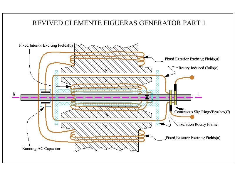
  • This is how I think that patent 30376 should be wound:

    Old times drum winding, as proposed by Figuera in patent 30376: Link


    Attached Files
    https://figueragenerator.wordpress.com/

    Comment


    • c are sliprings, hh axis of rotation but keep in mind that shaft is not movable
      Last edited by boguslaw; 06-02-2014, 05:18 PM.

      Comment


      • Originally posted by boguslaw View Post
        c are sliprings, hh axis of rotation but keep in mind that shaft is not movable
        Hello Boguslaw, I remember you from the Don Smith thread, are you suggesting that the central shaft is stationary, and the drum rotates independently, driven from another Source drive?.

        Regards Cornboy.

        Comment


        • Originally posted by Cornboy 555 View Post
          Hello Boguslaw, I remember you from the Don Smith thread, are you suggesting that the central shaft is stationary, and the drum rotates independently, driven from another Source drive?.

          Regards Cornboy.
          Sure. Imagine a drum with attached pipes. Imagine a quite normal dynamo generator armature, yet the internal electromagnets are not movable but shaft is fixed to armature in one side directly and in other side probably by kind of supporting metallic rods to allow drum rotor to freely move on shaft.That way both inducers outside (standard armature coils) and internal (fixed "rotor" coils) are not moving at all while a drum with coils rotate in field between them. Obviously you need sliprings to tap generated power. I see how this idea was copied along the century and resurfaced in patents like Robert Alexander in arond 1970 (and probably many more ).

          P.S. Drum is rotated by a pulley. For simpler prototype you only need a drum with pipes attached sliding on the shaft with a some amount of grease.

          If you have good mechanical skills I encourage you to build such generator , I'm pretty sure you won't be dissapointed (though it would require some hard work). A few problems need to be solved especially the minimal space between running drum and coils, coils connections, sliprings and so on. It's all beyond my possibilities and that makes me sad...
          Last edited by boguslaw; 06-03-2014, 10:55 AM. Reason: add some comment

          Comment


          • Quoted text from patent 30376
            Last edited by hanon1492; 06-03-2014, 02:31 PM.
            https://figueragenerator.wordpress.com/

            Comment


            • Hello hanon, UFO

              Hanon, first we should understand the rotated drum device before we proceed to the fully Motionless device-powered with two phase 90deg alternating current.

              This device which is describe here, is already been debunked by me and UFO Politics. The outer rim is the steady, motionless EVEN Magnetic Poles- This is just a single 1 copper wire wound in a Zig Zag fashion on a Circuilar E core form. Tesla used 16,32,64,128 until to 384 magnetic poles. The winding on the outer rim is the Zig Zag fashion. Tesla stated that the Zig Zag will create a North- South on Every Core it passes- that makes him possible to attain the 384 magnetic poles on such a very small machine which he always used to show on every demonstration.

              The rotated drum has a grove there wound a Soft Metal- Tesla used the Bessemer steel IRON wire as the suitable core. The Induced Coils wound on the PIN that hold the Iron wire core, is approximately 4 feet. The winding of the Induced coils is estimated to be 1/4 of a 1 ohm as Tesla stated. Tesla has always showed us a device that can produce a efficiency that is greater than 100percent.

              Imagined, you rotate it very slowly but have already produced massive energy on the output.

              This device is not shown in any patent but has been describe in a detailed once.


              QUOTE=hanon1492;256901]Quoted text from patent 30376[/QUOTE]

              Comment


              • Link to pdfThe key for avoiding dragging is the use of two opposite poles to generate the induction in the intermediate wire: N -- | -- S ; in contrast with common generators with just one pole exposed to the induced wire.
                induction created between two electromagnets, instead of common induction with just one pole exposed. IMHO, This is the key of his discovery.

                I attach a schematic of the generator (patent 30376) done by Ufopolitics. Also I attach an sketch with the representation of this principle. Please study this sketch and tell your comments.


                Link to Sketch (image): Figuera no drag principle

                Attached Files
                Last edited by hanon1492; 08-27-2014, 05:25 PM. Reason: Link to one picture added
                https://figueragenerator.wordpress.com/

                Comment


                • Originally posted by hanon1492 View Post
                  I am not as versed as you are in the mainstream viewpoint. Nor am I familiar with the Figuera patent. The reason for my posting is to say that I agree with your present finding, using two poles instead of one. This is something that I have been advocating for some time now, unfortunately my ranting has been falling on deaf, or better closed ears. One of the things that I have found is that in the gap we have a unidirectional flow. How we interact is paramount! The text book offers no direct suggestions, however, an open minded view of Faraday and Lenz's law reveals that a possible solution is in what we are discussing right now, namely, use both sides of the magnet, or use two poles when one both sides of the magnet aren't practicable. It can also be suggested that we pay attention to the coils reaction to the magnet, for it tells us everything we need to know!

                  I built a motor/generator which capitalizes on one way flux. The device operates as a reduced to drag free generator, or when operated as a motor, depending on the direction of rotation, the induced aids the supply. If indeed we are talking about the same thing, and of this I have no doubt, Figurea and many others, had it right, UFO doesn't belong to the group of those who know. He was very close in the early days, but lost the connection when all started worshiping him. I tried to share this and many other things with him, he thinks I speak in code so he missed it.

                  Thanks for confirming what I feel I have demonstrated to be true. The only thing you have to do now is build it, verifying your theory! I am looking forward to seeing what you come up with!


                  Regards

                  Comment


                  • After studying the Figuera and Buforn patents for over a year I have come to a few conclusions regarding this particular patent. It has some good points and bad points.

                    The magnetic flux inducing the current can be much stronger, more ampere turns, potentially higher output.

                    No expensive electrical steel or soft iron required.

                    There is no iron in the armature and the armature is not part of the magnetic circuit.

                    Lower induction losses in the armature compared to toothed barrel wound armatures.

                    No eddy current losses in the armature core.

                    Possibly little or no concern for 'back ampere turns' in the armature.

                    However, since the armature rotates there will be some power consumed to accomplish that. Also increased amp turns also means higher copper costs, but since x amount of amp turns will induce x amount of current I question whether that is a real improvement. In this design the air gaps in the magnetic circuit are much greater so the reluctance will be much higher and require more amp turns to begin with. Perhaps that is what necessitated the dual coils to begin with? Maintaining rigidity in the armature windings also looks like it could be an issue.

                    Whether the advantages of this design outweigh the disadvantages is questionable at this point, but I look forward to your results.

                    I have a feeling that Figuera wanted a patent to sell and he built a generator like this, but I believe his later patents and those submitted by Buforn were improvements on this idea.

                    Regards

                    Comment


                    • WRONG ! Where do you see armature rotating ? The essence is that NO SINGLE IRON part is rotating ! That's what let us "don't kill the dipole" because N S N S N S electromagnets are in steady state position, never changed but forced mechanical action. That is precisely stated in the patent.....the 90% or more of mechanical energy is used to overcome magnetic attaction and repulsion due to lenz law and that point is eliminated as indirectly Figuera stated.
                      Surprisingly the later patent is nothing more then eliminating the last minor problem..... Got it ? there is really nothing complicated (except it require precise mechanical skills to replicate it)

                      Comment


                      • Comment


                        • Sorry,Cadman I misunderstood you. By armature I mean the external soft iron casing with coils cores protruding from round shell to inside. If you thought about rotating drum-coil then fine.
                          Hanon already posted the correct explanation which means that Lenz law is nothing more but magnetic fields interactions and by combining two of them in Newton III law we can have zero force on electrons and zero Lenz law drag.

                          Comment


                          • Hi all,

                            This same principle is also used into Hogan and Jakovlewich overunity generator (see this link to the Hogan & Jakovlewich patentthe invention consited of a motor, a generator and a kind of governor or regulator. The whole system being so simple that a child could work it."

                            - A motor generator --> a device as described in Figuera patent 30376

                            - A governor --> maybe to regulate the motor speed, or to feedback the motor with part of the produced current

                            Please see in this link the thread of Hogan and Jakovlewich generator:

                            Hogan and Jakovlewich generator thread
                            Last edited by hanon1492; 08-09-2014, 10:52 AM.
                            https://figueragenerator.wordpress.com/

                            Comment


                            • Hi everyone,

                              About the patent from 1908 with the variable magnetic fields (which is radically different from those filed in 1902):

                              I have found a video which (I think) presents the ESSENCE of the Figuera motionless generator.

                              In this video it is presented the motor version where the coil is energized to create motion. But, the very same concept can be used to create a motionless generator. If you create two magnetic fields and you swing them back and forth then an induced current will be collected in the intermediate coil.


                              Therefore a motionless generator can be built with two variable magnetic fields without moving any piece at all !!

                              In the video two magnetic fields with LIKE POLES FACING EACH OTHER are used. (this patent from 1908 is radically different from those filed by Figuera in 1902 and that he sold to a banker union). The same Youtube user has more videos where he optimizes this idea: closing the magnetic circuit and adding more magnets increase the power of this device without using any more input current.

                              We should try every possible pole configuration N-N, S-S, N-S,... Remenber that Figuera did not stated explicitly the pole orientation. He used the notation "N rectangle" and "S rectangle" but he never said North nor South (which I found really weird). He did not clarified the exact pole orientation in any part of the patent nor in the patent claims. ( Link to patent text )

                              Please post your comments. I think that this video it is very interesting for everyone to think deep in this device.

                              Regards

                              Attached Files
                              Last edited by hanon1492; 08-14-2014, 06:53 PM.
                              https://figueragenerator.wordpress.com/

                              Comment


                              • One small historical pearl from one of the Buforn patent's that you all will love.

                                INPUT: 100 Watts ( 1 Ampere @ 100 Volts )

                                OUTPUT: 20,000 Watts

                                In other paragraph of the patent, Buforn states that the output was 300 A. Therefore the final voltage delivered by the 7 induction stages in series was around 60 V, more or less 10 V per stage.
                                .

                                Attached Files
                                https://figueragenerator.wordpress.com/

                                Comment

                                Working...
                                X