Announcement

Collapse
No announcement yet.

Re-Inventing The Wheel-Part1-Clemente_Figuera

Collapse
X
 
  • Filter
  • Time
  • Show
Clear All
new posts

  • Originally posted by hanon1492 View Post
    Maybe the reason for being a Lenzless generator is simply because both changes in the inducer currents are in oppositionN electromagnets is increasing while the current in the S electromagnets is decreasing we can say that their time derivatives are opposite : dI_N/dt = - dI_S/dt

    As the inducer field is calculated as N/dt = - dB_S/dt

    If both values can be added (I am not sure (please comment..)) dB_final/dt = dB_N/dt + dB_S/dt = 0 . Thus, althought there is a change in the primary magnetic fields (the cause of the induced current), the resulting induced magnetic field (the consecuence) -moving back to the electromagnets- is almost eliminated.

    Regards
    I think you got it right but that's part of story.

    Comment


    • Attached Files

      Comment


      • Originally posted by Cadman View Post
        As this drawing shows, the only magnetic collapse is from 1.714 V to 0 V (based on evenly split 12VDC).
        Hi Cadman

        In this link to a previous post you can download a simulation in Excel of the commutator. As you can see the voltage never drops to 0 V because always there is a part of the current reaching the farest electromagnet.

        About your suggestion of using a car alternator to make a test, could you specify how it is required to modify the coils to emulate a Figuera generator? A drawing will be very helpful. How you can emulate 6000 RPM as you mentioned in a motionless central coils?

        Regards
        https://figueragenerator.wordpress.com/

        Comment


        • Hi Hanon

          In the 1908 patent
          will not
          magnetize the electromagnets S because the whole resistance prevents it
          .
          Therefore, first electromagnets are full of current and the second ones are
          empty

          Comment


          • very simple, and is summarized as follows:
            1- From a AC signal apply a full wave rectification to convert it into two always positive waves. ( By using a center tapped rectifier you can obtain two series of signals: one coming from the positive half waves of the AC signal, and the other signal from the negative half waves of the initial AC signal ). Also you can create both series using a PWM, taking a derivation of its output to a NOT gate, and then two transistors to create two independient square signals.
            2- Apply a RL filter or a RC filter. This filter will smooth and will create a lag in order that both series of signals will be delayed and, thus, superimposing themselves. This way you can obtain the two unphased signals.
            Excel File

            Regards
            Last edited by hanon1492; 08-30-2013, 05:06 PM.
            https://figueragenerator.wordpress.com/

            Comment


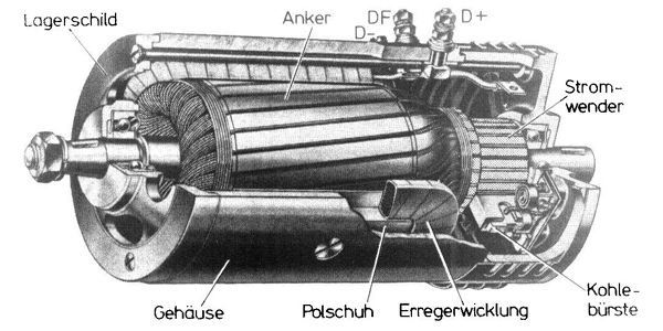
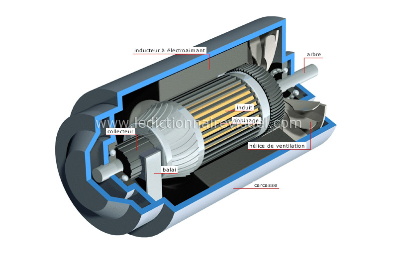
            • @Cadman: You talk of those old DC car generators

              Experts spend hours a day in order to question their doing while others stopped thinking feeling they were professionals.

              Comment


              • @JohnStone

                Yes. See the similarities? I believe Figueras 1908 patent is an improvement of this design.

                Cadman
                Last edited by Cadman; 08-31-2013, 03:18 AM.

                Comment


                • Hi Cadman,

                  I can see the similarity between the car-generators and the coil-arrangement in the Figuera patent and
                  Originally posted by Cadman View Post
                  Read the 1908 patent carefully and it is obvious that the only functional difference between the Figuera and conventional generators of the time was the method of varying the magnetic field strengths. Conventional generators mechanically rotating the entire armature and Figuera mechanically rotating only the brush.
                  I also think that this quoted description is correct.

                  Now let's concentrate on one coil-set (a set of primaries and a secondary) of this setup and then rephrase the available information:
                  Instead of building a conventional generator - a machine which is operated by mechanical force - Figuera build a generator which is operated by varying the voltage of the inducing coils.
                  OK.
                  That setup is a transformer, since a transformer is characterized by exactly this principle of operation.

                  If you agree, and if our conventional transformers are not over-unity, what then makes Figuera's transformer so distinctly different that it produces "more out than in"?

                  Can we name the principle that makes Figuera's transformer special - compared to the "perfectly engineered transformers of today"?
                  Last edited by marxist; 09-01-2013, 12:05 PM.

                  Comment


                  • Hi Marxist,

                    Call it a transformer or a generator. It doesn't matter because it works. I just finished a very small scale model to test my ideas. Three very small, tiny, coils driven with a Arduino gives me 9.2 VAC out. No moving parts.

                    With this one tiny set of coils I already have more than enough power to run my Arduino, just as Figuera claimed he could use to run his little brush motor. Another, or larger, set of coils should give enough power to supply the inducer coils and circuitry. At that point it will be self sustaining. Additional coils will provide surplus power, and then, if I don't encounter unforeseen problems, the generator will be over-unity and self sustaining. I believe that is what makes Figuera's generator special, just add more and/or bigger coil sets to obtain more power. It's only a matter of scale because it will take little or no extra power to generate more power.

                    The secret, if you need one, is

                    Comment


                    • Hi Cadman,

                      Can we have a look at your setup?

                      Cheers, Garry

                      Comment


                      • Originally posted by Cadman View Post
                        Hi Marxist,

                        Call it a transformer or a generator. It doesn't matter because it works. I just finished a very small scale model to test my ideas. Three very small, tiny, coils driven with a Arduino gives me 9.2 VAC out. No moving parts.

                        With this one tiny set of coils I already have more than enough power to run my Arduino, just as Figuera claimed he could use to run his little brush motor. Another, or larger, set of coils should give enough power to supply the inducer coils and circuitry. At that point it will be self sustaining. Additional coils will provide surplus power, and then, if I don't encounter unforeseen problems, the generator will be over-unity and self sustaining. I believe that is what makes Figuera's generator special, just add more and/or bigger coil sets to obtain more power. It's only a matter of scale because it will take little or no extra power to generate more power.

                        The secret, if you need one, is
                        HI Cadman,
                        I agree with Garrypm , I am eager to see your schematics and/or pictures. In your post you said that with the 9.2 VAC you can run the arduino but later you say that another set of coils should give you enough power to run the inducer coils and circuitry. I understand that your inducing current is not included in the current used by the arduino. Am I right? Could you tell us which is your input current and your output results at this time?

                        Please give some details of your test. Your proposal of using a car generator is new into this thread. Maybe you have done some important advances so far.

                        Regards
                        https://figueragenerator.wordpress.com/

                        Comment


                        • Hello everyone!

                          Hanon, thank you very much for translating the Buforn patent and posting it along with the images. And thanks to Spain for not allowing the patent to 'disappear'.

                          I threw this generator together with what I had on hand. The 3 coils were taken from 12VDC DPDT relays made by Seimens, and some excess material was removed from one end of the coil bobbins to get closer spacing. The wire in those coils is very fine and hard to work with BTW, not much thicker than a human hair. I soldered 30 awg enamel coated leads to the coil wires. The core of the center or induced coil was cut from a steel rod, and the length of it is about twice the length of the coil. The rod could be better, it is too small and does not fit snugly in the coil. It's pretty sloppy actually. The end coils, the inducers, do not have cores. The rod is centered in the center coil and goes about half way into each outer coil. That configuration is important and looks just like the image in the 1908 Buforn patent. When I put cores in the end coils the output dropped a lot.

                          The circuit uses two NPN transistors as switches, one connected to each inducing coil, and each of those coils has a diode across it to deal with back emf, if there is any. Each transistor is switched by a PWM output (~5 and ~6) on the Arduino through a pull down resistor. Those resistors were removed from the same relays that furnished the coils. The Arduino UNO is powered by a 9VDC battery and the circuit and coils are powered by a little 12VDC 500ma plug-in transformer.

                          Not exactly 'high tech' stuff, is it.

                          I started by sending a smooth sine wave to the NPNs, as fast as the controller could make them, lowering the frequency in one coil as it rose in the other.
                          On the first run the output was a dismal 2.4 VAC. If you saw my posts in the thread at overunity there is one where I thought I had discovered Figuera's meaning about the 'egg of Columbus'. I also posted a model of the commutator. For the second test I changed the PWM output to 8 steps, simulating a voltage change at 45 degrees like my commutator model suggested. The volts went to 5VAC. Then I changed the frequency to simulate dwell at end of each wave like I had charted at overunity. I started with 5ms. Bingo! The volts went to 8VAC. Finally I started increasing the dwell and got to 9.2VAC with a 40ms dwell. The magnetic bias does swing back and forth like a pendulum, pausing at the end of each 'stroke'. BTW, I have no idea how much amperage this is producing, but it can't be much with these tiny coils.

                          Observations:
                          The center coil rod is loose. It appears to center itself while the gen is running, and if manually shifted even slightly off center the output power falls. If shifted too far it will shoot to one end like a solenoid and power almost dies.

                          I do not know the polarity of the end coils. The two outer coils are oriented in the same direction, as if the relays were stacked on top of each other. The center coil is in the opposite direction. Swapping the DC voltage polarity of an end coil will either raise or lower the output.

                          Some things yet to try:
                          Center coil rod of various lengths. Different winding directions on the end coils. Adding small magnets to the end of each end coil. Iron ferrite core. FWBR to run the Arduino.

                          The circuit diagram and pictures are attached

                          And this is the Arduino code at present.

                          Code:
                          const byte coilN = 5;
                          const byte coilS = 6;
                          
                          void setup(){
                            pinMode(coilN, OUTPUT);  
                            pinMode(coilS, OUTPUT);  
                          }
                          
                          void loop(){
                          
                            for(int i = 0; i<360; i++){
                              i = (i+44); // change steps to 45 degree increments
                              float rad = DEG_TO_RAD * i;
                              int sinOut = constrain((sin(rad) * 128) + 128, 0, 255); 
                              analogWrite(coilN, sinOut);
                              analogWrite(coilS, 255 - sinOut);
                            }
                            
                            delay(40);  //dwell time
                          
                            for(int i = 0; i<360; i++){
                              i = (i+44);
                              float rad = DEG_TO_RAD * i;
                              int sinOut = constrain((sin(rad) * 128) + 128, 0, 255); 
                              analogWrite(coilS, sinOut);
                              analogWrite(coilN, 255 - sinOut);
                            }
                            
                            delay(40);
                          
                          }
                          I would be very curious to see a scope-shot of the wave this makes.

                          Regards
                          Attached Files

                          Comment


                          • Thanks for all that effort Cadman.

                            Cheers, Garry

                            Comment


                            • https://figueragenerator.wordpress.com/

                              Comment


                              • Originally posted by Cadman View Post
                                ...
                                The core of the center or induced coil ....is about twice the length of the coil. .....
                                The end coils, the inducers, do not have cores. The rod is centered in the center coil and goes about half way into each outer coil. That configuration is important and looks just like the image in the 1908 Buforn patent.
                                Also thanks from me, Cadman, for all the work in testing and publishing the information about the results.

                                Comment

                                Working...
                                X