Announcement

Collapse
No announcement yet.

Re-Inventing The Wheel-Part1-Clemente_Figuera

Collapse
X
 
  • Filter
  • Time
  • Show
Clear All
new posts

  • Originally posted by hanon1492 View Post
    Link

    In fact they both have different wiring disposition but it can be one other implementation of the motionless generator described into patent No. 30378

    Regards

    PS. Also a curious video I have seen: TPU Secret - Steven Mark
    Hi Hanon

    Great find that patent. Related to creating a 3 phase supply, I hadn't realized that motor inverters converted single phase to 3 phase - my ignorance, but maybe others don't also know? Price-wise not too expensive:

    0.18kw, 1/4HP Single Phase In, Three Phase Out, Motor Inverter, AC Drive, NEW | eBay

    Regards

    John

    Comment


    • Figuera in Rexresearch.com

      The site rexresearch.com has included a page with many info about Clemente Figuera:

      Clemente Figuera in Rexresearch.com

      Regards
      https://figueragenerator.wordpress.com/

      Comment


      • Non Stop Researching Possibilities...

        Hello to All,


        I have been still working on this Patent...and there is still so much to it...you guys can not imagine...We can have it all...in One Machine...One Axle/Shaft...Motor and Generator...Isolated, NOT exchanging coils like My Asymmetrical Machines...that uses same coils...Nope.


        But, in the same token...We could use a strong Motor...and rotate the exciting fields as Permanent Magnets...while having "The Induced" static...just collecting the Energy and sending it through direct connections (no brushes)...and I meant to be strong...because it will have to just move the Magnets Mass...Inner and Outer......Small Tests...but, Big Proof that it does works.

        Regards to all


        Ufopolitics
        Principles for the Development of a Complete Mind: Study the science of art. Study the art of science. Develop your senses- especially learn how to see. Realize that everything connects to everything else.― Leonardo da Vinci

        Comment


        • Originally posted by hanon1492 View Post
          ( Link )http://www.free-energy-info.tuks.nl/ ), but it has some little mistakes in the connections. Please see the scheme I have attached to this post for a correct configuration.

          Circuit to create the unphased signals

          I hope this help
          Circuit to create the unphased signals


          Regards
          Last edited by hanon1492; 09-23-2013, 09:57 PM. Reason: Edited on the 23rd of september to update the circuit in order to correct a mistake: pin 3 in the second CD4017 must not be used.
          https://figueragenerator.wordpress.com/

          Comment


          • Originally posted by Duncan View Post


            Hi Duncan,

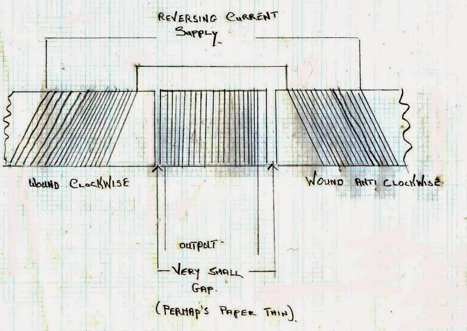
            After studying your sketch with CW and CCW wirings, I have realized that you are placing like poles in front of each other in the inducer electromagnets. Am I right in my interpretation? Can you elaborate your proposal a bit deeper?

            Thanks in advance

            Regards
            https://figueragenerator.wordpress.com/

            Comment


            • Dear all,

              How about if N and S does not mean North and South in the 1908 patent notation?

              I had already noted that in the whole text of the 1908 patent there is no reference where it is explicitly stated that "N" means North and "S" South. In fact it is just written: " Suppose that electromagnets are represented by rectangles N and S. Between their poles is located the induced circuit represented by the line “y” (small). "

              Regards

              PS. Maybe it was just a patent notation trick
              Last edited by hanon1492; 01-10-2017, 01:19 AM.
              https://figueragenerator.wordpress.com/

              Comment


              • https://www.youtube.com/watch?v=L_2G28531sI and again here by magnet flipper
                Magnetic Vortex Spin Demonstration by Magnetflipper - YouTubeSteven Mark solid state generator video 1 - YouTubeharmonics and overtones - YouTube
                Last edited by Duncan; 08-18-2013, 10:56 AM.
                Whatever you can do,or dream you can,begin it.Boldness has genius,power and magic in it.Begin it now.

                Comment


                • Originally posted by hanon1492 View Post
                  Dear all,

                  In the Figuera forum into overunity.com an user had commented that in his opinion N and S does not mean North and South in the 1908 patent notation. See his post here:

                  IMO I do not think coils S,N,Y actually meen south and north pole faces. Studying the layout closely I think the Coils S and N are facing each other with the same sign pole faces.The need for seperate core pieces is so the field caused by the pulse "on" travels through the other two coils opposite (y+n)or (s+n)so the direction of induction on the center coil and the off coil are the same. Current is added back in series with the on impulse acting upon the off coil through the power source. So if the on impulse was 12 volts + the field would project through the two other core pieces and coils.The reaction on the center coil would act like half a sign wave be it up or down. The outer coil which is off would induce in reverse direction of it's on state at a lower voltage or amperage but would add to the source voltage in series.A clever way to use as much of the field as possible drawing in and using the lesser force on the far side of the induced coil used to power the load. Im not sure if enough current could be produced to remove the starting power source or not. The only way that could work is if there is unequal abillity of inducing a magnetic field in a core piece when comparing voltage to ampere. Meaning if I use 1 volt and 100 amp on a core will it be the same measure of gauss field as compared to 1 amp and 100 volts using identical cores and windings. So that the load could be used in part as a source once it is started even if that ment it has to be stepped up or down to add to the impulse field the strongest magnetic field that it can produce without taking away from the productitvity of operating the load.Boy that was a ***** to explain that thought.
                  Hi,
                  recently I got a hint from another thread to this one being dedicated to Figueras.
                  Reading your text above I hooked up a 3 phase transformer Figueras like and now I dare to chime in in order to report some observations.

                  Test A: Tested with single pulses.
                  I agree with the notion that energizing one outer coil will generate in center and opposite coil a voltage pulse in opposite direction.
                  BUT: The voltage is about 3 times higher in center coil than opposite coil. Some notions:

                  1.
                  Of course a 3 phase transformer has 3 identical limbs and the magnetic "resistance" is higher in outer limb because of more distance to travel

                  2. I tested at 400V windings with 24V pulses. Therefore we are possibly in lower nonlinear area of magnetic graph. So it is understandbale that center limb is preferred like having two sinks to drain water.
                  At higher flux or connected load it might be different.

                  3. The smaller center limb in Figueras patent might be tuned in order to balance for flux.

                  Test B: I connected:
                  • half rectified AC (positive half wave) to first outer coil
                  • half rectified AC (negative half wave) to outer coil but reverse electrical direction.
                  PLEASE DO NOT WORK ON MAINS VOLTAGES - as long you are not trained and equipped for these dangerous voltages!

                  Possible next steps:
                  • Cutting slots in center limb with angle grinder in order to balance flux flow (between center / opposite limb). I have the strong feeling Figueras secret has something to do with a special kind of balance - either for input flux, output (Lenz) flux or both.
                  • Building FET drivers along micro controller in order to simulate Figueras commutator. In another thread a FET driver was built and the PCB is available publicly now. (maximum ratings 100A / 600V - others call it Monster Driver )) I just started a turorial for building and testing it step by step.
                    This info might help some of you. And NO: I do not earn any penny or cent for it. All is public domain.


                  I will not begin seriously with Figueras replication soon because I am active in teh other thread. But I decided to share my ad hoc notions with all of you.


                  BTW:
                  - Magnetic field as vortes see Howard Johnson
                  - Magnetic amplifiers do the very same like usual amplifiers (ok they might introduce some math functions...) - they act as a valve on an energy flow. They do increase amplitudes of a certain value but not energy.
                  rgds
                  John Stone
                  Last edited by JohnStone; 08-18-2013, 07:45 PM.
                  Experts spend hours a day in order to question their doing while others stopped thinking feeling they were professionals.

                  Comment


                  • moves on the magnetic field and returns from it by the two opposite INLET and OUTLET sides of the resistor." (Buforn patent No. 57955, page 12; Year 1914)

                    Until now we were thinking that the resistor has only one way (current going into the electromagnets). Maybe we were mistaken and the resistor is a doble way path for the electricity to come into the "ON" coil, and to return after being induced in the "OFF" coil if like poles of the electromagnets are in front of each other ....

                    Please share your thoughts about this proposal.

                    Regards
                    Last edited by hanon1492; 08-18-2013, 09:36 PM. Reason: Corrections
                    https://figueragenerator.wordpress.com/

                    Comment


                    • Originally posted by JohnStone View Post
                      HINT:
                      If somebody wants to tinker at a 3 phase transformer as well: Please get hold of one 400V/24V. At ebay there are plenty of them (ca. 100W....300W) Then you can isolate 400V contacts safely and work on 24V windings only.
                      Last edited by hanon1492; 08-18-2013, 11:04 PM.
                      https://figueragenerator.wordpress.com/

                      Comment


                      • TRANSLATION OF KEY PARTS OF BUFORN PATENT No. 57955 (1914) (text extracted from pages 12,13 and 14)
                        https://figueragenerator.wordpress.com/

                        Comment


                        • Is there any explanation about shape of commutator shaft ? I can't imagine how the contacts were made to efficently implement make before break schema.
                          Is there anything about the inducer coils connection in series ?
                          Why there is a box around the point of connection wire from commutator shaft to the power supply wire ?

                          Comment


                          • just a question

                            Hi folks, just started reading this thread ,am not up to speed.
                            In the diagram with the loose wires with multiple take-offs, is that some form of variable resistor?
                            That way changing the amount of current the electro-magnets receive causing flux intensity to change?
                            Just wondering, thanks
                            artv

                            Comment


                            • translation of bufon.pdf

                              Hi hanon,

                              I appreciate your great work on the forum.

                              Like Oliver I ask for more.

                              Is it possible to get the translation of the whole bufon document. I realize it is large doc maybe all that understands spanish in the forum could join forces.

                              Regards.

                              Comment


                              • Originally posted by boguslaw View Post
                                Why there is a box around the point of connection wire from commutator shaft to the power supply wire ?
                                VERY GOOD QUESTION !!! ????
                                https://figueragenerator.wordpress.com/

                                Comment

                                Working...
                                X