Announcement

Collapse
No announcement yet.

Re-Inventing The Wheel-Part1-Clemente_Figuera

Collapse
X
 
  • Filter
  • Time
  • Show
Clear All
new posts

  • #31
    Yes Wonju

    very nice explanation and documented

    easy to read and right place of picture is really helpfull

    well done

    for myself i tried some approach of the system

    here some pix of my preparation of a replication

    first pix are an idea to build the round tap system (not tested yet )

    So as you can see (pix 3 ) , i have made a serial of 2.2 k ohm resistor (10 time 220 ohms in serie with 10 tap connector places ) and tried to slide by hand ,back and forth a brush on the connector (red wire ).

    I got very different results depending of the coils

    here for eg 2 coils with armature from a microwave oven fan motor.

    As you can see i can not get a nice u shape wave , but more an inverted u wave shape.

    OK my very first test to encourage other on this system.

    good luck at all

    Laurent
    Attached Files
    Last edited by woopy; 10-26-2012, 10:45 PM. Reason: being more precise woth the resistor

    Comment


    • #32
      Woopy,

      I do not think the set up that you have will work satisfactorily. As soon as the brushes begin rotating, the plastic disk will not resist the friction and heat generated. If you want something reliable, you will need a commutator similar to this one:
      Commutator(Electric Power Tools) D21A - China Electronic and Digital Products Wholesale Center.

      Still, you will need to arrange for the brushes to rotate around it.

      There are different ways to generate the two quadratic sine waves:

      1) Rotating commutating switch. This is what Mr. Figuera used.
      2) Instead of a mechanical rotating switch, a series of switching transistor can be used to turn on and off sequentially. I like this approach more than the rotating brush. The driver for the switching transistors should turn the next transistor on prior to turning off the previous one. This option configures the transistors in a make-before-brake switching mode.
      3) A dynamo having the stator coils configured for 90 electrical degrees. If for instance, the stator has four poles spaced at 90 degrees, then, the electrical and geometrical degrees are the same. The two quadratic voltages can easily be derived.
      4) The easiest way would be to synchronize two inverters to generate the two quadratic voltages. I am trying to contact inverters manufacturers to find out if small inverters can be synchronized. I know that large inverters have this option to allow paralleling two or more inverters.

      If you decide to continue with the existing set up, please, let us know about the results. But, if it does not go the way you expected, DO NOT GIVE UP!

      Thanks for sharing.

      Wonju.

      Comment


      • #33
        No Permanent Magnets Needed!

        MR. FIGUERA'S INVENTION MADE OBSOLETE ALL MOTIONLESS ELECTRIC GENERATORS (MEG) BASED ON PEMANENT MAGNETS!

        ISN'T IT AMAZING???

        PATRICK KELLY WILL BE PUBLISHING THE PAPER ON MR. FIGUERA. HE DID A NICE JOB ON THE SKETCHES. I REALLY LIKED THE 3D VIEW OF MR. FIGUERA'S DEVICE.

        STAY TUNED! PATRICK'S WEBSITE CAN BE FOUND HERE:

        Last edited by wonju; 11-02-2012, 02:05 PM.

        Comment


        • #34
          I have only ever read the 1 news paper article before. good to see that Figuera is being brought into the light.

          Comment


          • #35
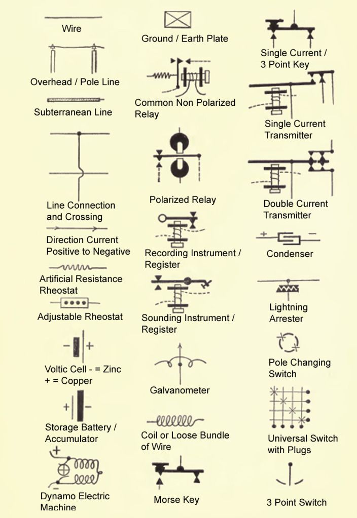
            Old Electrical Symbols

            Hi

            Maybe not totally relevant here but I have copied and added a key to an old chart from 1899 of electrical symbols. Of note is the different batteries and also loose coils of wire:


            Regards

            John

            Comment


            • #36
              Free-energy-info.co.uk

              REFER TO PAGE 19 OF THE DOCUMENT FOR A 3D VIEW OF MR. FIGUERA'S APPARATUS.

              Comment


              • #37
                Originally posted by wonju View Post
                REFER TO PAGE 19 OF THE DOCUMENT FOR A 3D VIEW OF MR. FIGUERA'S APPARATUS.

                http://www.free-energy-info.co.uk/Chapter3.pdf
                Thank You very much. I have a feeling that Mr Figuera is now smiling to us. He has finally been recognized. I think once we collect with respect all informations about inventors and their inventions from the past , we win battle for free energy. Forever....

                Comment


                • #38
                  TV-part I - YouTube

                  addendum ... It also gives this guys work a boost How Parallel Path Gets Over Unity ... doesn't it?

                  meanwhile I'll return to your interesting paper

                  Best wishes Duncan

                  PS A little further study seems to suggest that Joe Flynn and of course his system are now contracted and part and parcel of the American military system and all that realises D
                  .
                  Last edited by Duncan; 11-03-2012, 03:09 PM.
                  Whatever you can do,or dream you can,begin it.Boldness has genius,power and magic in it.Begin it now.

                  Comment


                  • #39
                    Hi Wonju and all

                    thank's for your recommendations

                    Here is a video of my really first approach of the Figuera system.

                    I wonder what could it be with modern transistor switching.

                    Hope this helps

                    Good luck at all

                    Laurent

                    generador Fiquera approach 1 - YouTube

                    Comment


                    • #40
                      Thanks

                      Wonja

                      Thanks for the new file and it looks really good in Patrick K's book.

                      Woopy

                      Great video, and its really interesting getting a square wave output - very unexpected. Do you know why?

                      Regards

                      John

                      Comment


                      • #41
                        Re-Inventing The Wheel-Part1-Clemente_Figuera-THE INFINITE ENERGY MACHINE

                        Comment


                        • #42
                          Hi Wonju and all

                          first thank's for all encouraging comments on the video.

                          And a very special thank's to you Wonju for the Arduino soft.

                          Already installed on my Freeduino board.

                          Now i have to design the transistors and resistors setup.

                          If you have already did this in practice, your help will be greatly appreciated.

                          What do you think of the rotating commutator results in the video, and especially of the square wave on the secondary under load ?

                          thanks

                          and good luck at all

                          Laurent

                          Comment


                          • #43
                            . What happens is that when rotating, the shaft slips through the oil contained in the bearings and rings with compressed oil. Under these circumstances, the oil acts as a dielectric forming a capacitor between the shaft (rotor) and the housing (stator). This capacitor charges to very high voltages when the motor is used with variable speed drives, and when a voltage limit is reached, it discharges through and damages the motor bearings. To make sure there is no voltage drop at the bearing, monitor the bearing voltage drop with the scope. If there is a voltage drop, modify the contact to touch the moving part of the bearing instead of the fixed shaft.

                            On the other hand, the switching transistors can be driven directly by the controller or through resistors. If the switching transistors are rated for the voltage and current used by the controller, then, there is no need to use gate resistors. This is a very simple scheme and you should not have too much problems with it. Later, I will post a diagram.

                            Thank you for sharing and keep recording and posting your results. We all enjoyed it!

                            Regards,
                            Wonju
                            Last edited by wonju; 11-05-2012, 01:11 AM.

                            Comment


                            • #44
                              @Wonju and Woopy

                              My question:

                              When stepping up and down the current through the two primary coils (in one coil the current increases, in the other coil the current decreases), should the current always return to zero between steps (which is the case when using a commutator)?

                              It is visible in Woopy's scope trace that the current returns to zero between steps (when switching through the resistors). And I indicated with a read line as it should be according to my thought (see the attached scope shot done by Woopy).

                              My thought:

                              The current in the primaries should increase/decrease continuously.

                              This can be realised by using a microprocessor

                              and a 2-Phase Motor Driver like the TCA3727 (can drive both primary coils, 6 steps = 5 resistors)

                              or two 1-Phase Motor Drivers like the LMD18245 (each LMD18245 drives one primary, 16 steps = 15 resistors).

                              In the attached data sheets see pages 13 and 19 for the LMD18245 (Quarter Step Drive with Torque Compensation) and pages 14 and 18 for the TCA3727 (mini step operation).

                              There are of course many different motor drivers and more modern ones than the ones mentioned by me (which I have by chance since some years).

                              It seems that in Wonju's Arduino project the current will also return to zero when switching through the resistors?

                              Greetings, Conrad
                              Attached Files
                              Last edited by conradelektro; 11-05-2012, 01:36 AM.

                              Comment


                              • #45
                                Are Resistors R Inductors?

                                Hi

                                I'm wondering if the resistor "R" are in fact a series of inductors, rather than heat producing solid resistors?

                                Regards

                                John

                                Comment

                                Working...
                                X