Announcement

Collapse
No announcement yet.

Re-Inventing The Wheel-Part1-Clemente_Figuera

Collapse
X
 
  • Filter
  • Time
  • Show
Clear All
new posts

  • Originally posted by wonju View Post
    The original waveform shown in the first graph is about right when you have a pure resistive load. The inductance of the primary coils should distort the shape a bit.

    I have no comments for the second graph.

    The third graph is not correct. You are showing two sinusoidal voltages in 90 degrees out of phase. If you applied these two signals to full wave rectifier, then, you get the correct voltage that should be applied to the primary coils. The voltage applied to the primary coils should be half-cycle sine waves. Refer to figure 21 of the document.

    Wonju.
    Maybe the '0' at the beginning of the time line is misleading a bit It is 0 A of current flowing through a coil. the trace is a sample from a running cycle when it comes to time line.

    Just look at it graphically. It has the same shape as the current traces above, all of them have high and low peaks at the same time! The last one is a current trace as well, not voltage! At the minimum peak a small amount of current still flows through a coil as per schematic!
    I am proposing this type of DC-offset sinusoidal wave form as it is my belief that maybe Clemente was trying to do just that!: linear or maybe even sinusoidal current rising/falling through the coils but he only had those simple inductive resistors at hand at the time of building. We do not know the operating frequency and input coil's and resistive element's inductances to predict the waveform on the output. It might have been close to sine wave AC...
    Last edited by kEhYo77; 11-12-2012, 09:49 PM.

    Comment


    • Originally posted by wonju View Post
      Can you provide the advantages of your recommendations based on an analysis similar to the paper posted in this thread?
      https://figueragenerator.wordpress.com/

      Comment


      • Originally posted by wonju View Post
        Can you provide the advantages of your recommendations based on an analysis similar to the paper posted in this thread?
        https://figueragenerator.wordpress.com/

        Comment


        • [QUOTE=kEhYo77;214261]OK, so to better understand what we are dealing with here I have drawn a quick graph.


          Hi Kehyo77

          The first trace is about what i can get with my rotating commiutator and certain very high Ohmage coil (200 Ohms from fan motor taken out from microwave owen)

          But generally the wave is not so regular and is assymetric , i mean it climbs relatively as per your drawing and than it fall down sharply and approach a kind of ringing form.

          But the question is now is the voltage trace important or the CURRENT TRACE important.

          When i tried to get info from the Google translator of the Figuera patent , the important thing seems to be a PROGRESSIVE up an down current trace and i don't see any relation to a voltage trace. But perhaps the google translation is very bad ???

          OK going on the testing on my bench, and getting some better idea of the relation between the primary winding and the resistors stack value to get a nice repetitive U-shape CURRENT form.

          But until now no really impressive result on the secondary extarctable power

          OK hope this helps

          Good luck at all

          Laurent

          Comment


          • @hanon1492
            You are correct and the pdf documents posted concerning the Clemente device have many more errors. In any case there is only one person who's knowledge is relevant here and that is Mr.Clemente, he is the inventor and this is his creation. I believe it would be in everyone's best interests to stop chasing ghosts and listen to what Mr.Clemente has to say in his own words.
            Here is the correct wiring diagram.
            Attached Files
            Last edited by Allcanadian; 11-13-2012, 05:52 AM.

            Comment


            • Originally posted by Allcanadian View Post
              @hanon1492


              You are correct and the pdf documents posted concerning the Clemente device have many more errors. In any case there is only one person who's knowledge is relevant here and that is Mr.Clemente, he is the inventor and this is his creation. I believe it would be in everyone's best interests to stop chasing ghosts and listen to what Mr.Clemente has to say in his own words.
              Here is the correct wiring diagram.
              I am ok with your diagram. In reality it should no matter how the diagram is shown. The important issue here is that the connection must generate a primary row with South Poles and the other with North Poles. And I think that is understood and clearly explained.

              In addition, please, feel free to point out any errors in the document. That is the purpose of this thread. It will make it better. Thanks.

              Wonju.
              Last edited by wonju; 11-13-2012, 02:37 AM.

              Comment


              • Laurent,

                Could you let's know the wire sizes of the coils and the number of turns?

                What is the rated voltage and current of the primary coils?

                Thanks, Laurent.

                Comment


                • Originally posted by wonju View Post
                  I am ok with your diagram. In reality it should no matter how the diagram is shown. The important issue here is that the connection must generate a primary row with South Poles and the other with North Poles. And I think that is understood and clearly explained.

                  In addition, please, feel free to point out any errors in the document. That is the purpose of this thread. It will make it better. Thanks.

                  Wonju.
                  Draw your attention to the red and black wires in AllCanadian's version of the diagram.

                  Red and black flip at the mid-point.

                  Which diagram is more accurate?

                  pt

                  Comment


                  • FREE ENERGY # 35 BI-TOROID TRANSFORMER - 377 % OVER UNITY MOTIONLESS - YouTube

                    also this thread opened by member vidbid regarding the Bi-toroid. Which if nothing else gives good construction idea's


                    Magnet Transformer (free energy) - YouTube39F Don Smith Device Project: BITOROID IN SELF-LOOP, CONCLUSION ANOMALY - YouTubeTV-part I - YouTube

                    TV-part II - YouTube

                    TV-part III - YouTube
                    all in all I think it fly's dont you? I wonder at the moment if some 3ph off the shelf transformers isnt a way forward A'la the transverter
                    Best wishes Duncan
                    Whatever you can do,or dream you can,begin it.Boldness has genius,power and magic in it.Begin it now.

                    Comment


                    • Solenoids Electro Magnets and Electro Magnetic Windings 1921

                      Wonja

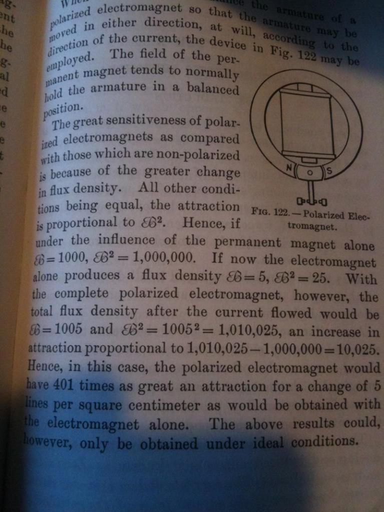
                      I hesitantly post up this book extract, from Solenoids Electro Magnets and Electro Magnetic Windings 1921. A few items I have been looking at recently appear to use flux switching as the energy gain. Whats of note here is combining the field of a permanent magnet with an electro magnet, and the attraction strength in the example increasing by 401 times for a small input.

                      Comment


                      • Originally posted by wonju View Post
                        Laurent,

                        Could you let's know the wire sizes of the coils and the number of turns?

                        What is the rated voltage and current of the primary coils?

                        Thanks, Laurent.

                        Hi Wonju

                        Sorry but i tested so many config that i cannot be precise on this question

                        but i can report that i have tested

                        Primaries in Fan motor from Microwave Oven , probably more than 30 AWG and much more than 1000 turns.

                        Than i have built primaries with 1000 turns 0.3 mm (about 28 AWG) and tested step up secondary of a lot of AWG and also step down

                        So it seems that all config reach to different results.

                        So feel free to test all what you have at disposal . anyway it will help.

                        I am going on , snaking in the technology , as per per my habit , and i am still very bullish on this kind of system

                        don't know why

                        but really BULLISH

                        good luck at all

                        Laurent

                        Comment


                        • External link with a revised version of the translation

                          Attached Files
                          Last edited by hanon1492; 10-09-2013, 09:12 PM. Reason: Edited: Included a link with a revised version of the english traslation. the attached file contains a newer version of the drawing with better resolution than the one the previous revision.
                          https://figueragenerator.wordpress.com/

                          Comment


                          • Originally posted by woopy View Post
                            Hi Wonju

                            Sorry but i tested so many config that i cannot be precise on this question

                            but i can report that i have tested

                            Primaries in Fan motor from Microwave Oven , probably more than 30 AWG and much more than 1000 turns.

                            Than i have built primaries with 1000 turns 0.3 mm (about 28 AWG) and tested step up secondary of a lot of AWG and also step down

                            So it seems that all config reach to different results.

                            So feel free to test all what you have at disposal . anyway it will help.

                            I am going on , snaking in the technology , as per per my habit , and i am still very bullish on this kind of system

                            don't know why

                            but really BULLISH

                            good luck at all

                            Laurent
                            SOMETHING I WANTED TO ADD: IF THIS DEVICE WORKS, IT CAN BE USED WITHOUT PAYING FOR PATENT RIGHTS! THE RIGHTS EXPIRED LONG TIME AGO AND IT IS IN PUBLIC DOMAIN!
                            Thanks,
                            Wonju
                            Last edited by wonju; 11-14-2012, 01:03 AM.

                            Comment


                            • Originally posted by hanon1492 View Post
                              Hi all,
                              Here is the traslation of the last patent of Clemente Figuera from the original text in spanish ( )

                              ----

                              PATENT by CLEMENTE FIGUERA (year 1908) No. 44267 (Spain)

                              .................................................. ........
                              Hanon,

                              Thank you very much for the information! You are doing a job that takes a lot of time and effort.

                              Regards,
                              Wonu

                              Comment


                              • Originally posted by john_g View Post
                                Wonja

                                I hesitantly post up this book extract, from Solenoids Electro Magnets and Electro Magnetic Windings 1921. A few items I have been looking at recently appear to use flux switching as the energy gain. Whats of note here is combining the field of a permanent magnet with an electro magnet, and the attraction strength in the example increasing by 401 times for a small input.
                                John,

                                Please, do not hesitate to post your views.

                                It sounds interesting. But, I still don't understand how the "flux switching" can generate the extra energy. Can you expand on your concept? How would you compare a polarized electromagnet, which uses Permanent Magnets, with the Figuera's apparatus that doesn't?

                                Thanks,
                                Wonju

                                Comment

                                Working...
                                X