
stupidity
Omg ! You people have serious issues and completely ignorant beyond belief.
I have never met a bunch of complete idiots in one spot as i have on this thread.
I really feel sorry for you people.
Complete morons to the third degree. Just look at the way you people are acting.....
It's revolting.
-
Resistors test one (1)
Hello all,
[VIDEO]https://www.youtube.com/watch?v=Y0byPvqzr5M[/VIDEO]
RESISTORS TEST 1
Here is a small test I have made based on my 300Watts Power Resistors...10 Ohms, and Nine (9) of them total...
Basically, since the Primaries are such low resistance the wave is following an alignment and NOT at opposed positioning...but both waves are following same flow.
However, still I get an Induction at Secondary...
Have a nice evening All.
UfopoliticsLeave a comment:
-
Do not measure only the resistance in your primaries but the total impedance. Maybe you could be surprised if your total impedance in your primaries is over 10 ohms while its resistance is just 0.5 ohmOriginally posted by Ufopolitics View Post
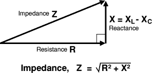
Where the inductive reactance (XL in ohms) of the coils is:

In case that you really had 0.5 ohm impedance in the primaries you should change your resistors by others with less that 1 ohm.
Or maybe try this other configuration from a heater of 1 KW to tune your regulator easily. Shadow may help you, it is one old picture from him into ou dot com:
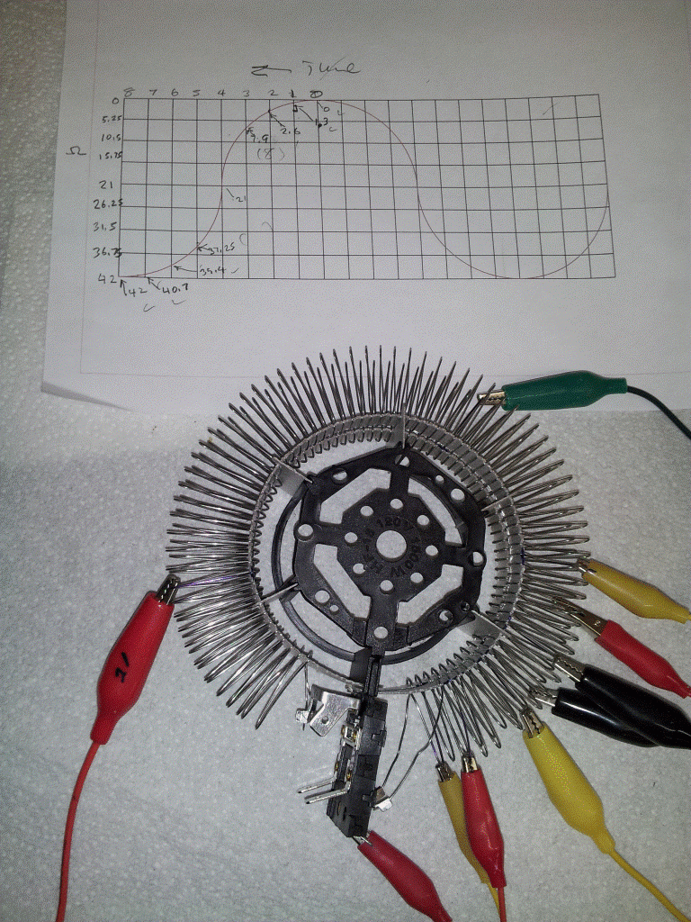
Does anyone know an easier method to tune the current regulator than this? I mean to perform fast tests and know for sure what are you using as total resistance in those tests...not for final design.Last edited by hanon1492; 12-29-2016, 12:30 AM.Leave a comment:
-
Bistander;
Because these builders always think BIG they probably can never make small tests? And verify before blowing the horn.
Regards ArneLeave a comment:
-
Bringing a strawman into the discussion
I was not talking about the core and I certainly never said that the size and depth of the core was of no meaning. That is just a diversion tactic from you because you have no evidence or suppprting research to back your flat conductor claims.Originally posted by marathonman View PostLeave a comment:
-
Ufopolitics is "just copying" what I have posted before!!
You are welcome to do that if you wish. This is the OPEN THREAD.
ArneLeave a comment:
-
Plus You... approaching like I EVER needed to get EVEN closer to your piece of crap approach!!...Originally posted by seaad View Post
This is just called Audacity, plus egocentric personality...from your end, underestimating everyone around you.
Doncha know...that I know by now the game you are trying to play?
Ufopolitics is "just copying" what I have posted before!!

Do you really think I need to copy an Ant's little, tiny work?
Imbecile!!
UfopoliticsLeave a comment:
-
"It is the number of turns that matter"
And i suppose more bs from you as the size and depth of the core have no meaning.
you people are funny.
i laugh daily at the things that flow from your mouths.
MMLeave a comment:
-
Nope...same N><N arrangement...and no need for so many wires or dual contacts brush either...I can excite them BOTH with same exact rotary switch as I have now, just one brush...Originally posted by seaad View Post
So, please, I do NOT need to "come closer to"...nor copy absolutely no one here, much less from you, ant...and never seen before your diagram...
I've got MY OWN FULLY DEVELOPED BRAIN...no ant one here.
UfopoliticsLast edited by Ufopolitics; 12-28-2016, 07:43 PM.Leave a comment:
-
Flat wire inductance test
Thanks for the verification. In simple terms:Originally posted by seaad View Post
Inductance is the SAME for wide flat wire vs small round wire.
It is the number of turns that matter, not the shape of the wire cross section. And as can be seen in the example cores from MM vs others, the flat wire limits the number of turns (wraps or winds) which is counterproductive IMO.
Regards,
biLeave a comment:
-
Are You coming closer to This?? http://www.energeticforum.com/293642-post1342.html. . . http://www.energeticforum.com/293662-post1347.htmlOriginally posted by Ufopolitics View PostLeave a comment:


Leave a comment: