-
Agree
Hi Hanon, I'm with you on seeing cancellation.
The only way it wouldn't would be to have an opening in the center ,where the coil could cross over to the opposite side, the coil shaped like a figure 8??
Hi UFO, That drum design is interesting ,but having a hard time understanding How would the coils be wound?
The Hogan gen wouldn't it be a lot easier to just have an entire pole facing its' opposite, with a coil between, then another magnet N Ca S Cb N ,So coil A supplies output to a load ,Coil B supplies output to a different load , and the back emf caused buy both coils being loaded would cancel each other???
artvComment
-
Nope...
Hello Shylo,Originally posted by shylo View Post
Nope, do not complicate your mind...lol, keep it simple first!
First, analize how coils are induced in a typical generator as we know...use the wires you do not like...Hi UFO, That drum design is interesting ,but having a hard time understanding How would the coils be wound?
 or "horizontal" ones... and make them in your mind of a flexible, elastic material...while keeping the vertical, usable for induction ones, rigid...then play with them. spread them along profiles...and you will see that this "cancellation" happens in everyone...it is just that you keep looking in the "past"...or the coils that ALREADY were induced...and yes, they cancel afterwards...but still conduce from the "ACTIVE" ones at the right timing "Momentum"...
There is an AREA on this design, where poles are sweeping fully each coils...then they induce...then stop...while NEXT one comes in...and in nano seconds of rotation.
NOPE...if you only have one pole at each side...there would never be a "Change" of Magnetic Flux direction happening at coils...therefore..."No Induction"...or "No Money no Laundry"...The Hogan gen wouldn't it be a lot easier to just have an entire pole facing its' opposite, with a coil between, then another magnet N Ca S Cb N ,So coil A supplies output to a load ,Coil B supplies output to a different load , and the back emf caused buy both coils being loaded would cancel each other???
artv
Regards
UfopoliticsLast edited by Ufopolitics; 12-15-2013, 03:19 PM.Principles for the Development of a Complete Mind: Study the science of art. Study the art of science. Develop your senses- especially learn how to see. Realize that everything connects to everything else.― Leonardo da VinciComment
-
I like this design...
Hello to All,
I believe this design, as all others have great potential...
Could you stop thinking about the "cancellation" and think where is the B Field from Induction projecting towards?...At what Angles related to the Exciter Fields?
Is it interfering or counter forcing rotation...creating magnetic drag?
Answer those questions first...
I believe those are more important issues...
The only way to test what kind of Flat Disc Drum Winding will work best...only in real practical, building it...will tell you guys...thinking about it will not solve anything but overheat brain.
This Patent could use tons of Improvements, plus extending design to several discs, several induction coils...more energy...
Regards to All
UfopoliticsPrinciples for the Development of a Complete Mind: Study the science of art. Study the art of science. Develop your senses- especially learn how to see. Realize that everything connects to everything else.― Leonardo da VinciComment
-
Hi Ufo , hannon and all
Very interesting stuff, this Hogan generator
So i have tested something
first i have installed 2 magnets with opposite polarity on my drilling machine.
Than i have taken the secondary of a MOT and put it on the side, and let the magnet spin very near, and i get a very nice sine wave on the scope. (pix 1 and 2 )
Than i have installed the same coil on a free to spin wheel, and shorted the coil to see if Mr. Lenz is acting and it seems he is, because the coil spins on the wheel., If i unload the coil, it doesn't spin at all.
Than i have tried a very thin coil, it works also very well. (coil on the right of pix 3 )
Finally i wound a coil in 360 degree, it i get a very bad and very very weak sine wave. (pix 3 ).
Voila
Hope this helps
LaurentComment
-
Nothing like REAL Testing!
Excellent Woopy!Originally posted by woopy View Post
Nothing works better than REAL TESTING!
Only way to find out...so all lazy guys get to work and stop tinkering!!...
By the way...I believe a kind of a whole "Conical Design" like you have woopy, on Pix 3...with higher center build up, due to wires accumulation...so, making magnets tilt a bit creating a Conical "Umbrella" type design at each end of shaft will cover all coils parallel closing air gaps...
Guys, think for a minute...so many Patents telling Us it does work...back from many years ago...trying to prevent what we are doing every day on Symmetrical Generators run by Farting Gas Engines...or having "Face to Face" Interactions, Face to Face both B fields (Exciting and Induced) colliding and creating huge drag...doesn't this tells you anything?!
Thanks again Woopy!
Kind Regards
UfopoliticsPrinciples for the Development of a Complete Mind: Study the science of art. Study the art of science. Develop your senses- especially learn how to see. Realize that everything connects to everything else.― Leonardo da VinciComment
-
Hi all,
This is how I think that this patent may work fine. I a modification to solve the problem of cancelling the opposite effect in each side of the coil in the original drawing (IMO). The winding is exactly as drawn by Ufopolitics previously; this is a type of classical drum winding which crosses the center point diametrically.

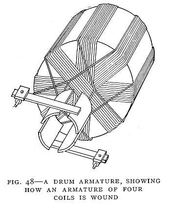
Image: Image
In my oppinion the key is :
1. A coil perpendicular to the inducer magnetic fieldStatic wires and moving magnetsLast edited by hanon1492; 06-02-2014, 02:50 PM.Comment
-
Thank's Ufo
It is my way to get each day something more to learn and or experiment.
So this one made my day, and i am of course addindg this idea to my general research.
Hi Hanon
good drawing but i don't see how you will insert and fix the diskmagnets inside the wound drum ?
good luck at all
LaurentComment
-
May The Force Be With You. May The Force Assist You
For deep study:
I think I have discovered a new configuration which may get OU finally. I want to share with you that in a configuration with like poles facing each other the induced magnetic field will not act against the inducer field (as usual) but it seems to reinforce the inducer field in the electromagnet which is increasing in strenght at that moment. In other words: the induction take place to ASSIST the inducer field, not to reduce it, as usually happens in the Lenz effect.

The important idea is to note that induction can take place as consecuence of two different phenomena:
1- Induction by flux cutting the induced wireInduction by flux linking two coils
In order to emulate a movable generator into a motionless device it is necessary that the magnetic flux lines cut the induced wires. Therefore we should maximize the induction by flux cutting and minimize the induction by flux linking.
Like poles facing each other: By changing the magnetic strength in both electromagnets (excited with the two opposite signals) the lines of force will repel and will leave the induction iron core. The sequential change in both currents will create a swing of the lines of force back and forth in each cycle, cutting the induced wires which surround the induced core.
The features that will require this configuration are:
Feature 1. Two north poles facing each other N-N in the electromagnets: With this set-up the magnetic field lines will leave the core inside-out. (Maybe two south poles will also work fine. I have just studied the N-N configuration)
Feature 2. Excite with two opposite signals each electromagnet . It will achieve a relative movement of the flux lines cutting the wire back and forth along the whole coil length from side (pole) to side (pole) (that we will name as coil thickness). One magnetic field is increasing and other magnetic field is decreasing, therefore no change in magnetic pressure between them will be created during this swinging motion.
Feature 3. A rectangular shape in the electromagnets an in the induced coil in order to maximize the flux cutting induction and minimize the flux linking induction. The ratio of both effects will be increased with high values of the induced core perimeter and low values of coil area. This is a new feature which is fundamental for a optimized induction.
Feature 4. As the flux cutting induction just happens in the zone where the lines are expelled from the core then we need that each turn will be cut during all the time. Therefore, it will be better to wind the induced coil with a tape instead of a wire (the tape must cover the whole coil thickness from side to side). With a tape all the turns will be cut all the time by the flux lines coming out the core. This will not happen with common wires. Tape winding will maximize the flux cutting induction and will minimize the induction by flux linking. I think that tape winding is mandatory for achieving a ratio well over 1.
Conclusion: With this new features I think that this generator will be able to get a much higher induced current than the current used to excite the device. The Lenz effect in this configuration will reinforce (assist) the inducer field which is increasing at that moment in the corresponding electromagnet. This configuration will get the Lenz effect working to make a stronger field instead of making a weaker field, as normally happens.
Link to the PDF file
Other link to the PDF file
Please share your comments and ideas, and tell me if I have made any mistake in this reasoning.
Regards,
Hanon1492
ANNEX - Equations


Comment
-
Yep hannon
well done
so it would be the Figuerra system but with upper and lower coil set on the same "like " pole
So on the drawing of the very first post of this thread , instead of having on the upper stage a South pole and on the down stage a North pole, we should simply have (for example ) a north pole up stage and also a north pole down stage. ? Right ?
And of course a kind of progressive-regressive flipflop voltage between the both stage , inducing the center coil ??
Very smart thinking bravo
LaurentComment
-
Hi woopy,
Figuera did not defined clearly the pole orientation.
Literally he wrote in his 1908 patent: "Suppose two series of electromagnets represented by rectangles N and S."
This was all.
Is N and S the real pole orientation or it is just a patent notation trick?
Later on Buforn, his partner, filed 5 more patents and all patents say just THE SAME. Suspicious? After studying it deeply I am almost sure that it was just a patent notation to hide the real orientation while protecting it at the same time! The real orientation is N-N, In my oppinion.
The other misterious sentence in the original patent is: "As nothing moves it is not necessary to have round electromagnets or induced circuit".Again telling it but encrypting the truth. In this study I have shown the reason for a rectangular trasversal shape.
Regards and merry Christmas !Comment
-
Hi hanon
Well, Hanon, you know how I feel about the 2 phasePlease share your comments and ideas, and tell me if I have made any mistake in this reasoning. . I think you've done a great job in your reasoning, now gotta build and test. I was thinking more in this line, as well, I been slowed down lately, but this is something I will get to try. Still working through the rotating field.
Thanks for sharing your work hanon.
Merry ChristmasComment
-
Hi all,
I forget to clarify that the two opposite signals must change the intensity field but it is not neccesarry to reverse polarity.
Both signals must be always above zero voltage.

RegardsComment
-
-
Link to previous picture
We may get a transformer where the distance between coils could be adjustable in order to regulate the phase shift.

Welding machine: "The intensity control could be done by displacing the coil: It consists on moving away the primary and the secondary"
More links:
Paper about the Thomson Ring
Any comments? Please tell me if you think that this method could work properly. Thanks
RegardsLast edited by hanon1492; 12-22-2013, 11:33 PM.Comment

 Tweet
Tweet


Comment