
Originally posted by seaad
-
It works! A first quick test real fysical transformer with center core = toroid gave 87%
PS. More thoroughly tests later shows that the efficiency factor is very high but never goes above 100%, just some percent below. Sad!
ArneLast edited by seaad; 03-27-2017, 09:17 AM.Leave a comment:
-
Seaad,Originally posted by seaad View Post
NONE...but I mean not even one option would work.
Fields are completely DIRECTIONAL...FACE TO FACE.
Only way that "sideways" (90deg) would work...is If Field fluctuates or moves following or through the y core center line.
Keep trying...
UfopoliticsLeave a comment:
-
Another idea
Signals to N and S coils phase shifted 90 degrees. (sinusoid)
First 1/2 stroke:.....Bottom Y-coil a magnetic N passes in left direction.
............................Top Y-coil a magnetic S passes in right direction.
Second1/2 stroke: Bottom Y-coil a magnetic S passes in left direction,
...........................Top Y-coil a magnetic N passes in right direction.
Regards / ArneLast edited by seaad; 03-20-2017, 11:37 AM.Leave a comment:
-
Split Coils Tests
Originally posted by bistander View Post
Hello Bistander,
Thanks, it was a great learning experience to perform that test!!
I broke like a mid layer and split it, so I will call Coil 1 to the inner one next to core and Coil 2 to Outer, exterior one.
I did Two Test with snubber diodes (fly-back) preventing negative spikes to get back to source, this way the square wave is neat, no spikes on scope...HOWEVER, all power drops down considerably as it will be shown on tests results below.
Sorry guys, but this fact above tells us that driving coils on this set up through electronic boards (Solid State) will definitively bring down your Output Levels result, as we will need all switching FET's to be protected by fly-back diodes...otherwise will be replacing them like there is no tomorrow...that is just my opinion...unless we develop some other way, where FET's could stand Primaries Coils back spikes without diodes from Pulsing Positive to Negative Source.
OUTPUT SPLIT COILS TEST:
Coil 1 (Inner) Resistance= 8.9 ohms
Coil 2 (Outer) Resistance=10.0 ohms
Input 20V / 0.4A and raises to 0.8 to 1.0 A whenever UNDER LOAD /3558 RPM's
AC OUTPUT RESULT WITHOUT FLY BACK DIODES:
Coil 1= 22.8V / 0.380A
Coil 2= 14.6V / 0.406A
AC OUTPUT RESULT WITH FLY BACK DIODES:
Coil 1 = 14.5V / 0.271A
Coil 2 = 9.5V / 0.260A
BOTH COILS IN SERIES WITH FLY BACK DIODES CONNECTED
Coil 1 + Coil 2 = 24.2V / 0.167A (AC)
BOTH COILS IN SERIES WITHOUT FLY BACK DIODES CONNECTED
Coil 1 + Coil 2 = 39.5V / 0.237A (AC)
Things to note about this tests:
I tested the fly back diodes, since the linear PSU kept bouncing analog meter needles, while the very rough protection system kept bumping on and off during tests...plus the Scope Signal was perfectly clean...but as you all could see...the Induction performance decays considerably by adding diodes on this set up.
Input Amperage raises whenever the Amp meter shorts out either coils, or when an incandescent bulb is connected, the increase is around 0.4 to 0.6 Amps. No matter if fly back diodes are or not connected.
One Coil is COMPLETELY DEPENDENT UPON THE OTHER related to INDUCTION OUTPUT. Meaning, if I connect a Bulb to Coil 1, and it is nicely bright...when connecting a second bulb to Coil 2 Both DIM OUT considerably...Like SUCKING ALL POWER FROM MAGNETIC FIELD when both are ON and OCCUPYING THE SAME EXACT SPATIAL VOLUME where Field is Fluctuating.
At least to me...this Tests told me a lot of things...as am sure you will also draw many conclusions.
Many thanks Bistander it was a great idea to do that!!
I will be uploading some pic's of the tests above and add them to this post later on...so keep refreshing page if you wanna see them...
PICTURE BELOW:FLY BACK DIODES ON, nice Scope Signal, very clean...Output= 13.3 V :
[IMG]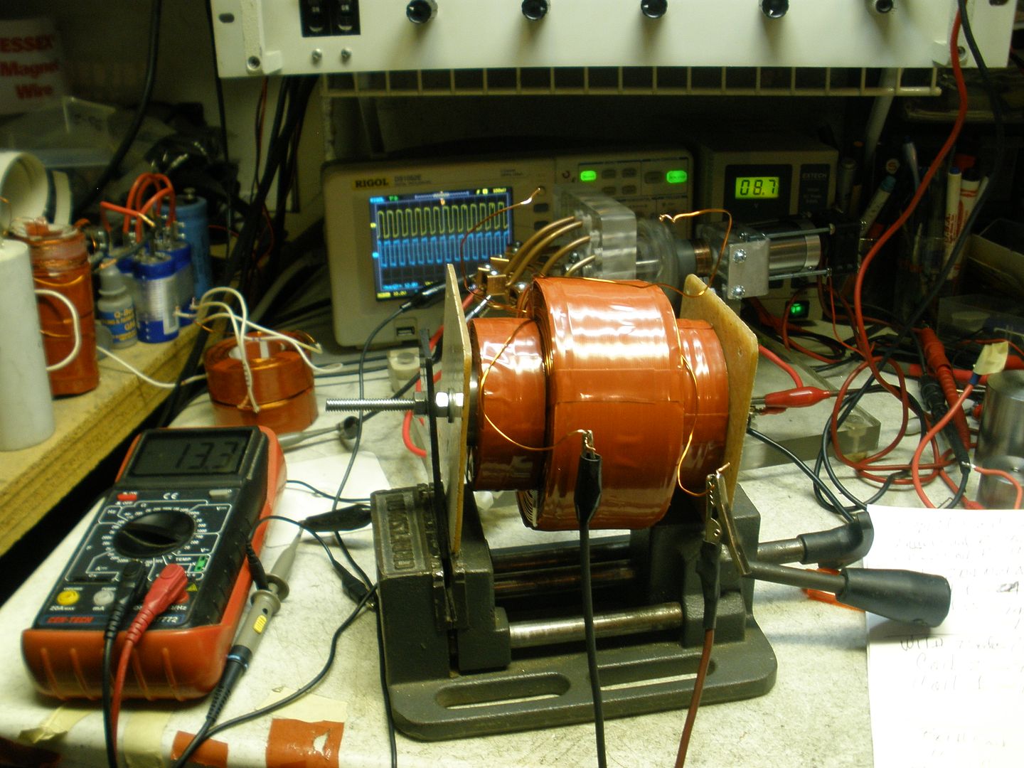 [/IMG]
FLY BACK DIODES OFF, SIGNAL SCRAMBLED BY SPIKES (Compare V Meter results at left, Output= 20.6V, Same Input, same speed as Pic above...):
[IMG]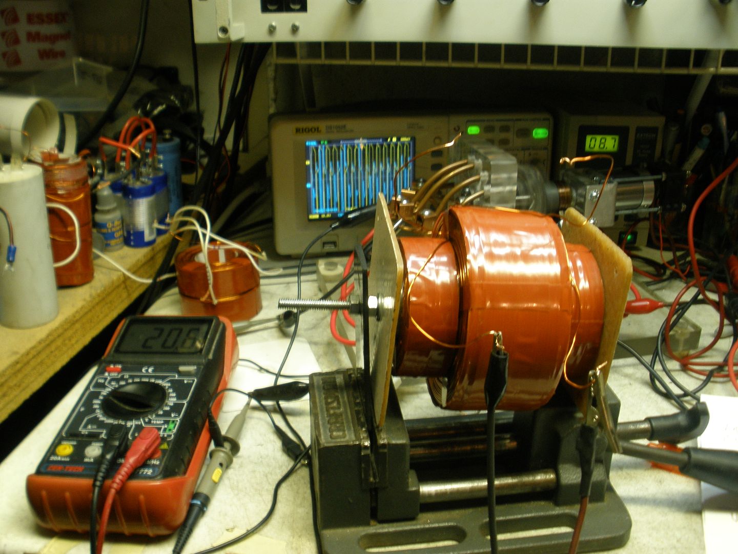 [/IMG]
NEAT SCOPE SIGNALS WITH DIODES ON...POOR OUTPUT RESULTS THOUGH:
[IMG]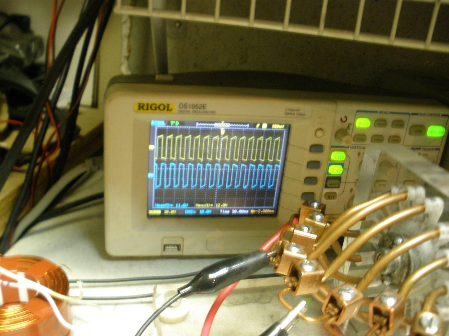 [/IMG]
LINEAR PSU OUTPUT= A bit less than 20 V and like 0.3-0.4 A:
[IMG]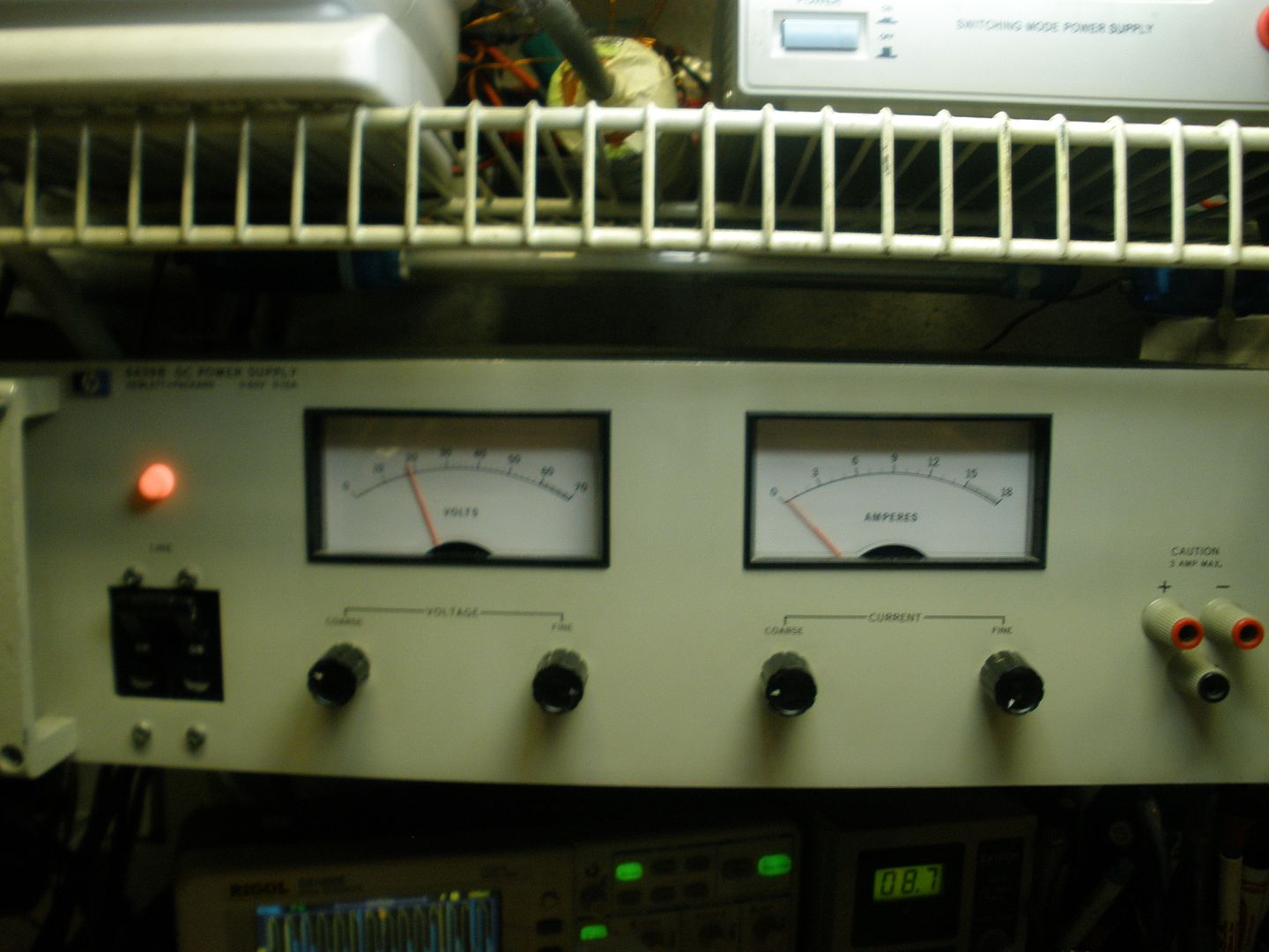 [/IMG]
Switching PSU providing Motor Supply to develop 3559 RPM's:
[IMG]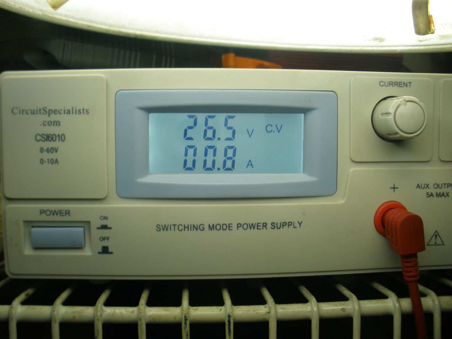 [/IMG]
Regards to All
UfopoliticsLast edited by Ufopolitics; 03-07-2017, 05:14 PM.Leave a comment:
-
Split coil
Ufo,
I was trying to keep it simple. No winding. Just snip a turn on the end of fatboy about midway from tbe core to the outer layer (like layer 18).
So after you cut that mid turn, you have two wires. One will pair with the original start winding to give you both ends on the inner coil. The other wire left at the mid point pairs with the outer end winding on the original coil to give you both ends to the outer coil.
You can always reconnect to two mid wires and have your original fatboy single coil. Or you can use separately the inner and outer coils.
biLeave a comment:
-
Hello Bistander,Originally posted by bistander View Post
Yes, agree with you, Fat Boy is too big for those exciting coils.
Yes, I do have access, it is just Tape and Copper...so, let me see if I understood, what you are saying is to cut at half way (leveling with Exciters end surface) and re make another coil with the upper end wires, starting from core right?
I like the idea, now the inner coil and outer would go all at center between both primaries? then one with resistor (maybe a diode as well to enhance field) and just one to retro-feed exciter coils?Originally posted by bistander View Post
I was thinking to make a couple less fat coils and half the one I have (1 In length) and leveled to exciters, in order to test with the diagram I showed before which would render more output power.
This Fat Coil is one piece from start to end through all 2 inches length.
Thanks
UfopoliticsLeave a comment:
-
Phantom load
Hi Ufo,
It sounds to me like your y coil (the fatboy) is over twice what's needed for those primaries (N & S). Is it possible to access a coil turn on like layer 18? Cut and configure for 2 nearly identical y coils? Use the inner y coil for your phantom load (resistor) and the outer y coil to loop thru bridge rectifier and filter (cap).
Just an idea....
biLeave a comment:
-
Thanks Hanon,Originally posted by hanon1492 View Post
I do not have the set up right now to do that kind of testing, related to an AC Transformer to reduce at the suitable V and A.
Not really complicated, it is the ONLY WAY to know if the Induced Power goes above the Exciter or Inducing Field(s) Magnitude and Fluctuations. Plus, also this will show the point of output where we have enough Induction Field as to go for the Secondaries.Originally posted by hanon1492 View Post
Yes, and so, the Induced Coil supplying power to retro-feed Exciter Coils would act as a Load.Originally posted by hanon1492 View Post
And what Doug said was that this system needs a "Phantom Load" to Operate properly, as he suggested it would be the "second secondary" which would always be retro feeding exciters, once we disconnect from the external source...and my "Fat Coil" is acting exactly as that...
Btw, I did a test with Ultra caps and it gives me much slower decay response which allows me more time to play with acceleration (RPM's) plus other adjustments, while showing increase-decrease by milli-volts accuracy of Caps on Digital Meters.
Regards
UfopoliticsLast edited by Ufopolitics; 03-06-2017, 10:19 PM.Leave a comment:
-
Ufo,
Your coils looks really great!!!!. You may try this simple exciting system with just four diodes. I am sure you will get a much better result that the one I got with my coils. Give it a chance.
http://www.energeticforum.com/294156-post1483.html (you can do it without the resistor R, which is just used to add a DC bias)
Looping back the output with caps toward the exciters to look for self-sustaining operation seems to be a much more complicated test than just measuring the coil output.
I think that Doug told that you need a load consuming output power to see the desired effect. Maybe MM can confirm if I remember it right.
Good luck.Leave a comment:
-
Working on the Self Excited System...
Hello to All,
Yesterday I made a Big Fat Coil...
Based on 20 awg, 1812 ft, (around 18 ohms resistance) and around 55 Turns per Layer, and a total of 37 Layers and the core is 1 1/2 in thick by 2 inches in length.
[IMG]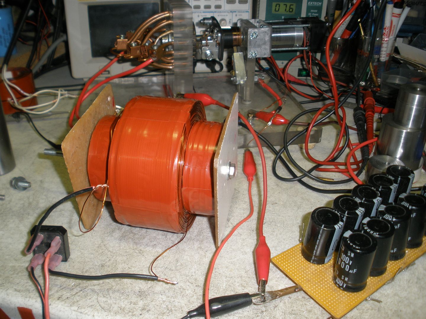 [/IMG]
And basically I am working first, on being able to achieve the exciter system to self sustain. Not concern at this point about Main Secondaries Output.
The two exciter Coils were the same one (1) inch long by 1 1/2 thick at 600 ft of 23 awg that I have tested before. And as seen on picture above...they are too small now, meaning, in Radial expansion compared to Fat Coil...
By giving 3600 RPM at 12V input to exciters, the Fat Coil could bank in DC with a Bridge rectifier over 60V.
However, when connecting Cap Bank to Source through a Diode at positive (->l +) to prevent charges to fly back to PSU....then slowly dialing PSU down...the Voltage can not keep on steady, it keeps coming down...gradually, and NOT FASTER than my dialing down, which is a good sign...means, it is retaining somehow...but still comes down.
And this tells me the Electromagnetic Field PULSES are STILL not strong enough in order to keep the system steady at 3600 RPM's or 60 Hertz when disconnecting PSU gradually.
And of course, if I increase PSU power, the Bank could get up to 100 Volts at 30V Input (and I do not want to go higher than 100V because Caps are rated right at 100V, but as I increase Input Banks keeps going higher)...However, it is NOT just a matter of STORED Increase being bigger than Input, BUT to INSTANT and CONSTANT POWER to be stronger delivered by the magnetic pulses, in order to keep up when we disconnect PSU.
I need to get the right RATIO of CONVERSION form steady 60 Hz Field Flashes or Pulses into Output power HIGHER DENSITY here, in order to achieve a Self Excited System.
Before I build bigger exciting coils, I am gonna try to add a couple of steel plates (of like 1/4 inch or bigger, whatever I can get my hands on...) as flares or "fenders" at the front of each exciter Core, in order to magnify field pulses into the Fat Coil.
And again, I am not trying to do "nothing out of this world" here...every Self Excited System Generator works this way, except, they use rotation force of the rotor field to achieve the field fluctuations...and we are using EMP's at same frequencies...so we need to get to a point where with a lower Input, we reach the right constant output power which later on would also Induce Secondaries.
"I have been here before" ...with my Repulsion Generator based on Permanent Magnets, where I had to keep increasing the strength plus number of magnets...However, if anyone have any suggestions would be appreciated.
My development continues...
Thanks and Regards
UfopoliticsLast edited by Ufopolitics; 03-06-2017, 04:27 PM.Leave a comment:
-
Originally posted by Ufopolitics View Post
Hello MM,Originally posted by marathonman View Post
On the quoted text by me above...I was referring to "Static" Repulsion Fields, not the Figuera case, in which case both repulse fields are in a "Dynamic State", meaning "moving" by whatever means we refer to...whether diminishing or increasing currents...or Physically displacing that repulsion field through Space-Time.
And here (on Figuera) you are completely right...as both fields form a single field vector of force, which moves towards the weaker of the two...being "pushed" by the stronger one.
Regards
UfopoliticsLast edited by Ufopolitics; 03-06-2017, 12:57 AM.Leave a comment:
-
Primary fields
Quote;
"But I can not, and so Classic Magnetism does not apply the same concept above whenever we have Two Like Poles, a North to North or a South to South. This contains TWO Vectors which does not "add up" to a Single Vector like with N-S approach, but contains Two Vectors Opposed in Direction, Magnitude could be the same or different...and so accordingly both Fields would react...but both vectors never add up, but repel each others...this is Classic Magnetism Theories...nothing new here Bistander."
They do contain two vector fields but the fields are in the same direction because one is reducing and the other increasing. both vector fields are in the same direction thus causing one large vector field. it is because of the lenz law that pressure is maintained between them and this pressure walls is what is used to sway the secondary field from side to side thus allowing the secondary to collect from this very strong vector field.
just my two cents.
MMLeave a comment:
-
Vectors
Good catch Ufo,Originally posted by Ufopolitics View Post
I interpret that center line in the diagram running between the N pole of each magnet to represent a series of B-vectors at every point on that line. Vectors to the left of the center point have a direction per the arrow head (pointing to the right) and vectors to the right of the center point have a direction the other way, to the left. At the exact center is a vector with zero magnitude therefore direction is irrelevant (ie. a null vector, I think they call it). So, if the magnets were indeed 100.0000% identical and you placed a test charge exactly midway between them, that charge would experience zero force from the magnetic field.
{2nd edit} I've been thinking more about this "center line" and have decided that it must be an error by the originator of the diagram. I much prefer to see the representation as done by Cadman in his femm where there is no center line shown. The lines in these drawings are often thought as lines of flux and therefore are convergent, meaning they close on themselves. Lines which exit the drawing boarder are expected to re-enter and close upon themselves. This doesn't seem possible with that N-N centerline so I suggest it doesn't represent anything real and should not be drawn.
{end of edit}
So no, a vector has a single magnitude and single direction at every instant in time. The vectors are used to define the field at every point. In real fields, this vector can change from one point to other point in the field. The directions of these changing vectors throughout the field is represented by the lines and arrow heads in those diagrams. In femm diagrams, they use colors to represent the magnitudes of the vectors at different points throughout the field.
{edit} I added that femm for reference. It was done by Cadman and posted on this thread earlier. He also has 2 more nice images. Lately I noticed those images have disappeared from his post. Too bad. I want to use them. If he reads this, please post those again. They can be helpful to us understand Figuera. Thanks.
Regards,
biLeave a comment:


Leave a comment: