
Taking it for a "Drive"...
Hello Guys,
Figuera's Rotary Switch Test 1
[VIDEO]https://www.youtube.com/watch?v=-UvHKfst38U&feature=youtu.be[/VIDEO]
Above is the video like I have promised before, same arrangement as I stated, 47 ohms resistors, around 12V Lipo Battery feeding it...and so on
It was a very quick video...just to see resistors are doing their job..let me know what you think?
Regards
Ufopolitics
-
Elcheapo,Originally posted by Elcheapo View Post
The rule you are using is for transformers, with flux linking induction as per Faraday equation E = N•A•dB/dt, but our dear Figuera generator is based on flux cutting induction as per Lorentz force E=v•B•Length•N, but in this equation just compute the number of turns that are cut in each instant while moving the colliding plane of both fields back and corth. That why I think it is preferable to have many turns cut in each instant therefore IMO it is better to have more layers in the induced coil than a long coil with few layers: more layers more turns over the moving plane between both fields. But this is just my guess, I can not assure if that is fine or not.
Ufo,
I tested a variac to mimic MM design of part G. It was not a rheostat as Bista der said. What I noted when tested the variac with DC was that it has a very complex behaviour. It seems to be a balance of different magnetic fields fighting inside the toroid. For example when I stopped the rotation after a few tenths of seconds the dimming changed as a response to the movement. I could dim each bulb completely with just around a third of a whole turn while moving the brush. I can not explain why but I saw a complex dynamic system. I think bistander is right about the variac response.
MM,
You are right. Big generators need avoiding big resistors and it is better a toroidal part G withou losses. But you are one step ahead. The rest of us would be very happy just with a proof of concept first. I have noted that you moved from a toroidal core design to a straight core. Is there a reason for that? I think the magnetic field in a straight core will be much lower than in a toroid, and then I suppose that the energy stored will be smaller, but I am not sure. I post below your design included in PJK ebook some months ago.
 Last edited by hanon1492; 09-11-2016, 09:18 PM.
Leave a comment:
-
Variac
Ufo,Originally posted by Ufopolitics View Post
It is not a rheostat, it is a variac, which is a variable transformer. The dial wipes on the turns wound on a magnetic toroidal core. As a transformer it is intended to be used on AC where it will provide a variable output voltage with a fixed AC voltage input.
The winding in the variac has very low resistance so on a low current circuit like with the two bulbs and a DC source has no effect in the steady state. However when the wiper is moving there is a changing current in the variac winding causing a voltage drop proportional to the inductance which causes one bulb or the other to dim, but only while the wiper moves. Once stopped, within a very short time (a few time constants) the variac has no affect on the DC circuit.
biLeave a comment:
-
Commutator part G
UFO;
Actually i am not using Nichrome wire on my final build, that is thick rectangle wire.
the Nichrome was used in my demo build with the cores i shared with Mario.
i didn't take a real photo but the paint pic below in the exact layout i used with Nichrome wire and demo cores.
16 segments were used.
Elcheapo;
looks like 240 winds i think, sorry note book is trashed.
for all you people looking for wire in the United States. the cheapest wire around is EIS WIRE. link....EIS - Electrical, Electronic, Wire & Cable, Industrial Assembly
they are but a few miles from my house so i don't pay shipping. yeh !
i have a question, if the Figuera puts out 15 kilowatts of power and powers it self then what would the COP be..........15,000 or what ???
MMAttached FilesLast edited by marathonman; 09-11-2016, 07:02 PM.Leave a comment:
-
-
Ops !
Mario;
You are very correct, the turns figure i posted is incorrect. let me check again. i know the primaries are right. note book drying out.
The thick commutator bars were actually thick wire or more then likely rectangle wire with not many turns.
my part G is being wound with thick rectangle wire to take up more space having less winding's. so Netica you are correct in your assumption.
below pic is for the people who wish to electronically switch the Figuera device.
UFO;
You have to remember the variac is wired slightly different then the figuera part G. the Figuera device is one continuous winding with N and S on either side and a rotating brush only.
MMAttached FilesLast edited by marathonman; 09-11-2016, 05:11 PM.Leave a comment:
-
-
Hello Hanon,Originally posted by hanon1492 View Post
I like the simplicity of that video...it shows the effect pretty clear.
However I have noticed when the rear bulb is dimming out... all the sudden the front bulb lights up way too much...which is not supposed to happen...I believe is when rheostat reaches the end points it "jumps" to max values.
The way I see the bulbs should behave is in even a smoother alternation...Dimming Bulb 1 to minimal values without allowing to completely go off...while Bulb 2 should start gradually increasing its brightness, all taking place in unison, sync.
I understand you are driving it back and forth, which is not the way it happens when a full rotation is applied.
Great viewing video though...we all could see the effect we are trying to reach here.
Thanks
UfopoliticsLeave a comment:
-
Hello Hanon,Originally posted by hanon1492 View Post
Thanks for your concerns.
I understand what you are saying perfectly well.
What am doing is just a test rig with what I have available...I do have lower values resistors, but not of high wattage.
If resistance is too high I will increase Voltage...until I obtain a Bulb lit at both ends. It is Sunday, so can not just go and get new resistors.
As I also look at your resistors chart with so many variable values...looks like a real nightmare friend!!
I know Figuera's drawing is very simple not only for better understanding, but to put it in the best "general terms" as possible.
I now understand why Marathonman chooses his VERY SIMPLE Core approach wound with Nichrome wire, making a "custom" round rheostat...where the wire windings will actually provide MUCH smoother signal than fixed resistance values...You see, at very high RPM's...these fixed values will never survive keeping an exact "ohms count"...it is based on real experimenting friend, not computer simulations...
[IMG]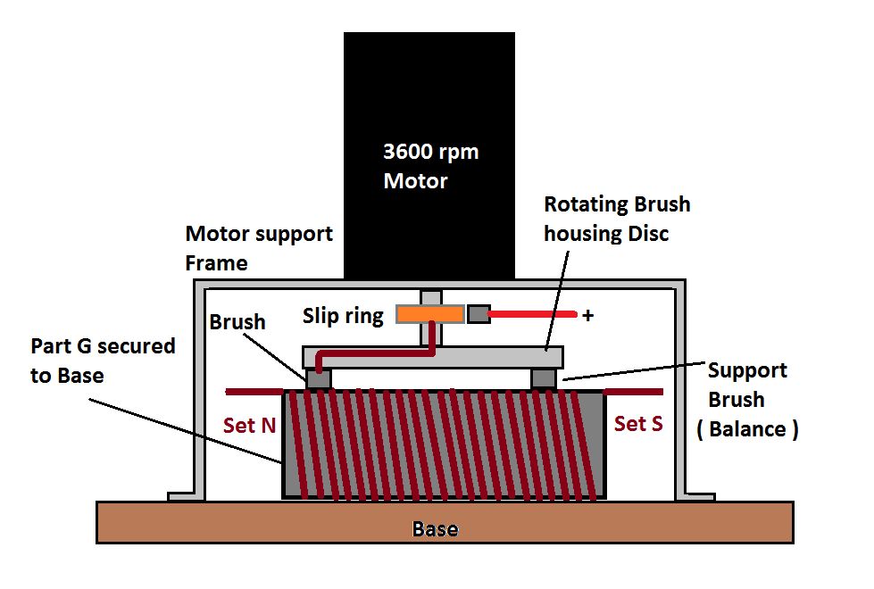 [/IMG]
And as a matter of fact, when higher speed is reached, your bulbs in your video will "barely" light up their filaments.
Now, I see you are adding diodes in your diagram...so you must account for each diode resistance right?
I am really applying what you have mentioned before...the KISS Approach:
[IMG]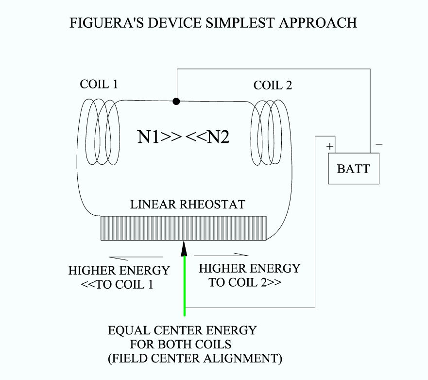 [/IMG]
Then see what I get at low and high ends.
Thanks much for your advice(s), I can see those signals and resistors values graphics have been carefully elaborated.
Regards
UfopoliticsLast edited by Ufopolitics; 09-11-2016, 04:12 PM.Leave a comment:
-
Tswift,
what I said before about connecting the coils out of phase is actually incorrect. While you still can use one signal only you have to drive the coils in sync. Meaning they both have to have their poles in the same direction (not opposing). While during one half cycle the coil on the left is pulling the left PM field towards and beyond the center, the coil on the right is pushing the field of the PM on the right back. Things are reversed during the other half cycle.
This timing is intended only for a setup where the basic opposing fields are created by opposing PM's which we could call the dc component, where the coils are used for modulation only.
MarioLeave a comment:
-
turns ratio
MM
Something in your demo that doesn't jive.
You say primary coil has 300 turns and secondary has 90 turns.
That's a turns ratio of 90/300 =.3
Since turns ratios and voltage ratios are always the same and primary
voltage is 50, then output would only be .3*50= 15 volts.Leave a comment:
-
Part G
While i won't stop anyone from building what they want, using resistors at 12 volt might be fine for a test rig, it is absolutely insane for a high power rig that puts out kilowatts of power. you cant put amps through a resistor fellas.
high power resistors are crazy expensive and get hot so you will have to rethink your idea when building those higher power rigs. to me it would be more practical to build part G that could be used for both.
below pic is an idea for you guys off the top of my head that would fulfill your needs.
just a thought.
MMAttached FilesLast edited by marathonman; 09-11-2016, 03:39 PM.Leave a comment:
-
-
Ufo,
If you are going to test shortly the resistors please take into account that Figuera represented a simplified commutator design to “make easy the understanding” as he literally wrote. I guess he could have used one commutator with two resistors arrays in parallel to get symmetrical signal to each set of coils. If you use just one array then the resistance in one side depends on the resistance in the remaining resistors in the other side of the brush contact. Therefore the two waves wont be symmetrical. Using two arrays in parallel you may get independent resistance in each array and therefore we will get symetrical waves. Some posts ago I linked an Excel file simulating one and two resistor arrays.
I know you love asymmetry but in this case I guess we should look for two symmetrical signals !!
BTW , 47 ohms in each step of resistors is huge. I will point more toward 4.7 ohm in each piece or even less, as low as 1 ohm, if you use the same value in all resistor pieces. And if you want to create a perfect sine wave I would use two resistors arrays with values as those included in the attached image

And below the case for just one resistor array, as drawn in the patent. Note that the higher the resistance of each piece the more asymmetrical waves will be obtained. 1 ohm is fine in each piece for a good shape with 12 V DC source and each set of coils with 7 ohms
Attached FilesLast edited by hanon1492; 09-11-2016, 03:26 PM.Leave a comment:
-
-
Let me guess...The Old Wild Turkey or Tennessee Jack Daniels ?Originally posted by marathonman View Post
I don't even "try" going there at all...not enough whiskey, beer or medicine that could do it...try being on OU, that will kill you.
MM
Take care, back to work
UfopoliticsLast edited by Ufopolitics; 09-11-2016, 02:23 PM.Leave a comment:


Leave a comment: