
 Tweet
Tweet
Originally posted by thx1138
View Post
-
Last edited by GSM; 11-15-2013, 12:27 PM. -
epoxy and neo magnets
Just an FYI the use of epoxies with steel filing such as liquid steel will effect the magnet's field strength. A clear epoxy usually works the best.Comment
-
like this? (from the base you can recover energy)
Last edited by wings; 11-15-2013, 07:52 PM.Comment
-
According to designs published it were the two short alu strips that were wrapped first over the thick paper layer, together with the thin paper and then the long alu strip.Originally posted by GSM View Post
(just making counternotes as I'm reading up on the thread to the end; if it was already spotted then I apologize)
Onwards!Comment
-
Hi Wings; Isn't that an excellent video !!!!!Originally posted by wings View Post
It demonstrates how independent oscillations can be 'reactively tuned' to become phase coherent.
Initiate an impulse in an AC soft iron circuit and the pendulums are always energised one way.
Remove the source and without load their moment (back-EMF) becomes a damped oscillation.
However;
where a core flips polarity about its physical macro 'neutral zone' position wrt a magnet,
this is a transducible one way - NON OSCILLATORY - event,
yet one which may be arranged to be continuously on-going,
via mechanical (Wesley Gary), electrical (Hubbard) or both methods (Hendershot) induction,
and where two pulses may be transduced for every single initial reversal energised.
This video demonstrates *continuous* two dimensionally resonant *oscillation*, where force and resultant amplutide become tunably phase separated in time, and where there will be a brief damped physical 'back-EMF-like' reducing to zero oscillation if the energy source is removed (all pendulums suddenly not driven but still free to swing).
Whereas Gary and Hendershot clearly use critical mechanical armature positioning to induce on-going Schmitt Trigger like magnetic field reversals, where the energy necessary for oscillatory mechanical energisation (Hendershot - resonant) is effectively mechanically decoupled from any of the reactively related armature-core-coil losses and back-EMF effects, the theory of which we are indoctrinated in via AC Theory 'education' !!!!!
Cheers ........... Graham.
.Last edited by GSM; 11-17-2013, 11:33 AM.Comment
-
Published by whom ?????Originally posted by pjotterkjen View Post
I have already mathematically established that Lester's noted 7,800pF capacitance relates to a foil overwind over cartridge paper thickness wrapped around the orignal coffee can cores he originally used !
I have also very clearly shown a photograph of a coil wire on a Hendershot generator going to one of the can cores = 7,800pF no matter how many foil turns were wound on.
Also I have already posted in this thread old words relating to a *single* aluminium capacitor winding over the tin core.
Only two core-cap connections were used by Hendershot in his original generators, these connected to the outermost lower tuning winding likely related to the *longitudinal resonance frequency* of the tin can cores he originally used !
All of the different aluminium capacitor instructions must be suspected as being deliberately diversionary.
Cheers ............ Graham.Comment
-
Epoxies with steel filings
I'm glad you thought of it. I wouldn't have. Thanks.Originally posted by Ruphus View PostComment
-
20 AWG insulated solid copper in L1 and L2
I got more info back from Belden wire from their 1941 catalog. They had a 20 AWG that had rubber insulation over a paper wrap and covered with a glazed cotton braid lacquered. The approximate O.D. was 0.100". I'm guessing either the cotton or the lacquer was colored to give the wire the red and yellow colors noted.
Today's PCV covered 20 AWG solid copper has an O.D. of 0.066". That gives us a difference 0.816" over 24 turns (12 each for L1 and L2) X .034". So that part is no longer a mystery. Just need to determine a way to make today's wire 0.100" O.D. The wire I linked to earlier was 0.120" to 0.125" so I'll keep looking.Comment
-
Magney Info
Can you share information on the magnet shown in post #173? Where you obtained it, overall size, space between poles, pole sizes, etc?Originally posted by john_g View Post
I'm putting together a parts list and am having trouble locating a suitable magnet. I can put together 10 pieces of neo magnets to make one but it's roughly $350 just for the pieces. That's more than half of the parts cost and I would like to get that cost down.
I did find some cloth covered wire that is 0.105" so that might have to do. The O.D. is not specified at the site but I left a message and they replied back with 0.105" O.D.
20 awg Solid Core, ClothLast edited by thx1138; 11-24-2013, 09:32 PM.Comment
-
Hi Mike, I have been reading up on this thread and saw that this was your last post; has there been any progress? I hope you didn't give up as your set up showed you were on the eve of some very interesting experiences...!Originally posted by mikec_ut View PostComment
-
I think that value is not a magic one. According to Arthur Aho (who spend two and a half year testing the device together with Hendershot himself) that specific value of 7,8 pF was NOT that important but yes (and this makes real sense to me) the two caps should closely match (taken from Aho's 1968 notes):Originally posted by GSM View Post
"Fitting closely to the inner circumference of this triple coil was a condenser which was rewound from an 80 mfd, 400 volt electrolytic condenser, but dried before winding on a metal ring. The final capacitance was not critical. Units operated anywhere from 0.006 mfd to 40 mfd, but they were critical as to balance. Each side had to be within less than 2% in value to the other."Comment
-
-
Limited time but still working on it
@pjotterkjenOriginally posted by pjotterkjen View Post
I have not given up yet. I didn't expect it to work on the first try but I wanted to get an idea of what it would look like. I did notice that the two coils inside the basket weave coil are really a magnetic compass equivalent. This lead me to study the 1920-1930 Magnetic Compass to see how they worked. This then lead to the fact that IMHO the schematic is backwards and works from the left to the right using the theory of magnetic amplifiers, so I have been studying Magnetic Amplifiers from the 30's and 40's. Too many unknown components that all work together but I am a sucker for dream technology.
The adventure continues.Comment
-
Core neutral zone field reversal.
Core neutral zone field reversal works only up until the iron core reaches magnetic saturation, which doesn't take long. After that time the core has it's own field and no longer responds to the neutral zone shift. This may account for the very brief running time of the Hendershot motor!Comment
-
More details, please
Great to hear that!Originally posted by mikec_ut View Post
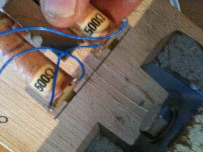
I'd like to see some better & closer pics from what you have built, and if you can include what specs you have used for each coil that would be awesome.
I was planning to start directly with the MKIII but thinking about all the devices I now am also inclined to first build the MKI and then progress, just like Hendershot did.
Although my knowledge is a bit rusty I'm an electronic engineer who studied also some radio engineering many years ago, I still have some real passion left for electronics and radio techniques. Besides that I'm a patient guy.
Awesome discovery about the magnetic compass, this would fit in extremely well since it was Hendershot's first goal after all - design a reliable compass that points to the real North (and work better than the induction compass). I'd have to pick up the specific knowledge also. If you have some good pointers to start that would be great.Comment

Comment