
Originally posted by HuntingRoss
View Post
-
Leave a comment:
-
Mark,
I just need you to keep in mind what I am quoting below from my previous post:
Any build that you make not complying with this main aspects above, honestly is a waste of time friend.
P2 is turning off too close to South Stator
And the Magnetic Influence from whole P2 coil 2, still will be opposing to rotation at those close limits under high speed rotation (Magnetic "Inertia").
They will render same results as you had before.
Regards
UfopoliticsLeave a comment:
-
Overlapped All North 12 Pairs
Originally posted by HuntingRoss View Post
Ok Mark, the Overlapped Coils in each Pair 'series'.
Four Poles:
[IMG]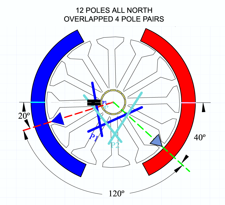 [/IMG]
Five Poles:
[IMG]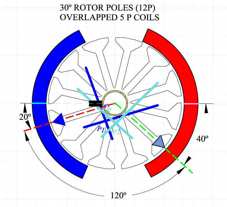 [/IMG]
Note that it reduced the interacting angle from bisector to bisector from 150 to 120 degrees.
However, notice in order to keep about same angles, when winding five poles you do need to overlap grabbing two poles from first coil, instead of just one in four poles coils.
IMPORTANT: I forgot to set the Brush at 11 degrees for this two IMGS, so, consider that, or rolling one element back for comm element connection, which ever is easier.
Nice hunting!
UfopoliticsLast edited by Ufopolitics; 04-13-2015, 06:43 PM.Leave a comment:
-
My pleasure Mark...Originally posted by HuntingRoss View Post
Like I wrote before, I am also doing this (while leaving everything else in "stand by") in order to clear this whole scenario that dates back quite some time by now...
I already did Mark...One way or another I will CAD this tomorrow to demonstrate what I'm saying.
Right, agree 100% with you.There is one thing I should seek absolute clarity on...and this could be the difference between what you're saying and what I'm understanding and this would remove all the frustration.
That's right, P1 is "just" starting to touch commutator plate that corresponds to that circuit...take a look at CAD below:When we say 'connecting' or 'start firing' we mean the comm is just entering the brush...
[IMG]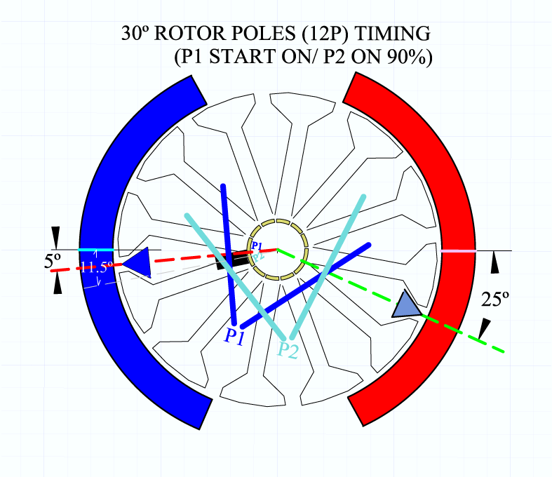 Yes, correct...commutator plate is NO LONGER contacting brush...is OFF, Circuit Dead.When we say 'disconnecting' or 'cease firing' we mean the comm has fully left the brush...
Here is the CAD result:
[IMG]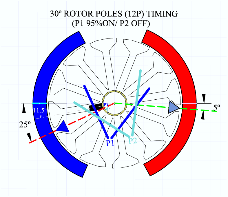 [/IMG]
Like I wrote before...you have a very narrow angle within LIMITS to do your adjustments here.
However, there are many easy solutions to fix this problem, and I will show at the end of post...
Mark, the MAIN part I would like you to understand basically out of ALL this, is that by no means, once you visualize your CAD, and Rotate its Rotor objects together...you must never allow that P2 Coils 2 passes the South Bisector while is still ON!!P2 is turning off too close to South Stator
And the Magnetic Influence from whole P2 coil 2, still will be opposing to rotation at those close limits.
Therefore what I highly recommend Mark, is to take a good look at this previous post I did four pages back...OVERLAPPING ALL NORTH PAIRSLast edited by Ufopolitics; 04-13-2015, 05:27 PM.Leave a comment:
-
Mark, you could download Draft Sight, from that link, which is free of charge and excellent software, I have it as well as Auto CADOriginally posted by HuntingRoss View Post
Mark, no matter if I misled you by giving you that center arrow between Pairs...even though, right after I repaired the "damage"...I was trying to get a common 'convention point' to align timing on this motors...but hey, I was wrong, We can NOT do that...But it does not means I ignored that each coil has its bisectors right at center of its geometry.Now I am willing to admit there exists the possibility that I'm wrong, but I shall try to express this in words and maybe knock out a sketch later as an image.
[IMG]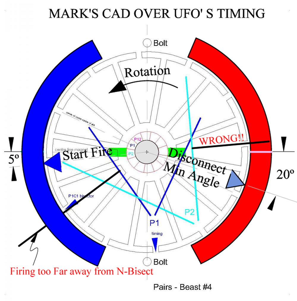 [/IMG]
However, in ANY part of Asymmetrical Machines you keep ON, A NORTH COIL PAST the SOUTH Bisector, because that is going to do just like stepping on the brakes pedal all the way to the firewall of your car.
And that is Exactly what you are doing in your CAD over My CAD in above Image.
You are keeping P2 ON PAST South Bisector...that is a no, no, nope...never do that!
Plus, your Model have Dual Rotors attached together...plus Double set of Stators...so your "brakes" were just like the Brembo used on a 250+MPH Enzo Ferrari...made of carbon fiber discs and carbon fiber pads...plus vacuum and electrical assisted...
Mark, let me ask you this...on your CAD, did you made that rotor and commutator/elements plus Coils into a Group, plus center align and ROTATE IT related to Brushes and Stators?...Only then., only IF You rotate this CAD's Rotor You will be able to catch all other coming interactions almost like in reality.
I can't make the math permit the 4 pole pairs to be configured 'correctly' despite the Team Spokesman chanting the mantra.
Happy Hunting
mark
Mark, take a look at picture below...
[IMG]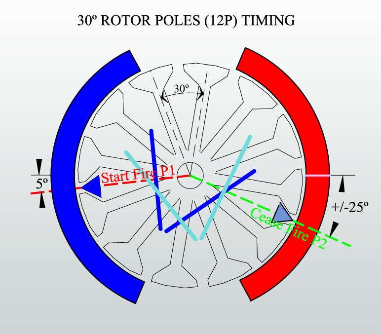 Last edited by Ufopolitics; 04-12-2015, 04:11 PM.
Leave a comment:
-
All very nicely put Sam. I have given up trying to do time consuming 'absolute torque' tests favouring instead the quick and dirty indicative tests...the tether test shows a weak motor quickly and accordingly can be disregarded from the search for optimum performance.Originally posted by sampojo View Post
Happy Hunting
markLeave a comment:
-
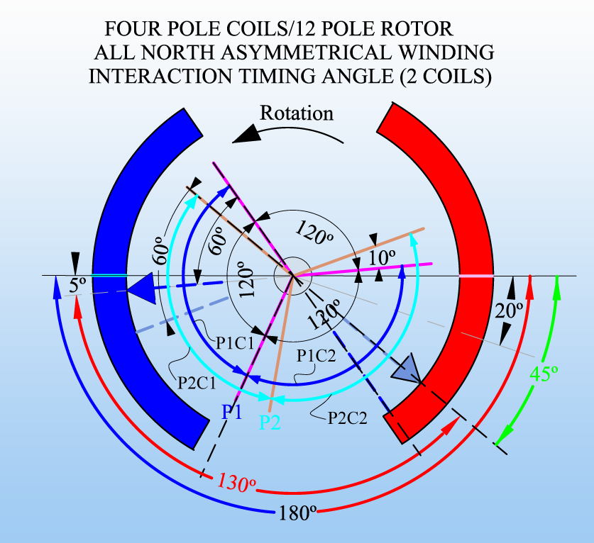 [/IMG]
Take a good look at it, First note that all interactions are taking place mostly on the 'Southern' hemisphere of both Stators, P1 Coil 1 to Bisector of P1 Coil 2 P1C2 Bisector to P2C2 Bisectorend line to start line ofLast edited by Ufopolitics; 04-12-2015, 01:42 PM.Leave a comment:
-
Some thoughts on torque and comparing Edison to Tesla motors.
A lot of questions arise regarding torque and how to compare symmetric and asymmetric motors, and of course Gchilders and Hunting Ross even comparing various asymmetric embodiments. You guys are simply stellar in your efforts.
Torque is obviously a difficult measurement. Gary's and Ufo's annecdotal observations have provided believers solid demonstrations. If we were design engineers in the lab at Baldor or Imperial Motors, all the best equipment would be at our finger tips, in a multi-million dollar facility. Imperial has had a wake up call thanks to Ufo's, Prochiro's and Midaz's efforts there. If they aren't doing anything, their curiosity and creativity is simply lacking.
Since Ufo has clearly cracked N. Tesla's patents and revealed the simple genius of design in isolating coils and come up with the fill-in-the-blank-Tesla-left windings. The result is now motors with NO CEMF. Me and Midaz were hanging around the diyelectric car forum, and those jokers who pretended to understand electric motors could not get it through their thick heads even when I quoted from my US Navy Personnel Manual on electrical systems and such, how CEMF voltage rose with RPM until it matched the battery voltage, opposing it, AND THAT IT WAS A BAD THING. They went on to mystically accept how it was a necessary part of the motor process of converting electricity into motion. Edison, Morgan and Lorentz went a long way in sanitizing the minds of engineers in colleges everywhere in their time and all curiosity regarding motors seems dead.
So of course, preaching to the choir here, a symmetric motor, voltage for work will be battery voltage minus CEMF. Since an Asym motor gets an extra kick at TopDeadCenter, when the coil rolls off the commutator, from Mother Nature's Back EMF on the coil, lets call this Assistive EMF or AEMF. So Vw=Bv+AEMF.
This of course is the secret to the potential of overunity here. Is a coil BEMF from the energy put into the field of the coil by the battery or are we opening a portal to the zero point energy or ether energy field. As a physics major possessing a masters in engineering also, well aware of modern advancements, I know of no absolute way to confirm that the assumption of conventional wisdom can be absolutely demonstrated. Furthermore, Ufo's Post 3132 seem to disprove conventional wisdom. Anytime more energy can be garnered as in an open system, it would actually disprove the conventional wisdom that the rules of conservation of energy apply to the electric motor, as a closed system. The fact that the BEMF occurs in complete isolation from the battery, that its energy is from the battery can actually be viewed as somewhat of a leap of faith...
This difference of a plus on one hand vs. a minus on the other is quite a huge difference, as big as it gets mathematically. Anyway, a symm motor has its max torque at zero rpm, topping out when friction and CEMF forces are equal and opposite to battery power. In an asymm motor, torque will be constant as provided from the battery voltage, but most likely increasing as AEMF increases with rpm, and then rpm will only stabilize when friction equals energy generated by Vbatt + AEMF.
Therefore simple comparisons of max rpm's at matching input voltages in my analysis is a very good test. But the only way any motors can be truly compared is that they match in their general composition and they're both designed to run at roughly the some max voltage in continuous operation without melting down. In other words best vs. best, until someone puts a team of engineers on it with millions in funding.
As we know Ufo has always recommended packing the rotors with as much copper as possible. Until I opened my Baldor motor, I had never seen a totally packed OEM rotor. Of course an OEM motor was designed for a certain task, and to have put more copper in it would probably be a waste of money for the job it was built to do. Or they use a fan in the motor to force air through the rotor, and they leave the rotor's partly empty to allow air flow. This may be a weakness in the design of Edison motors as Ufo constantly points out how the coils in his motors rests and cools until next firing. So be it, then, that would be a limiting factor in comparisons, advantage asym. But if the original motor rotor was designed weak for the application, and the asym motor is maxed out that would not be a good comparison. We should keep an eye out for this condition in our comparisons.
Great work, men! Keep it up.
SamLast edited by sampojo; 04-12-2015, 06:24 AM.Leave a comment:
-
Hello Mark,
I must say you are a funny guy...made me laugh about your comments...
Now, related to the four poles... I am really sorry to say this....but I think you are calculating the bisectors at wrong positioning...or something else ...I made this CAD below:
[IMG]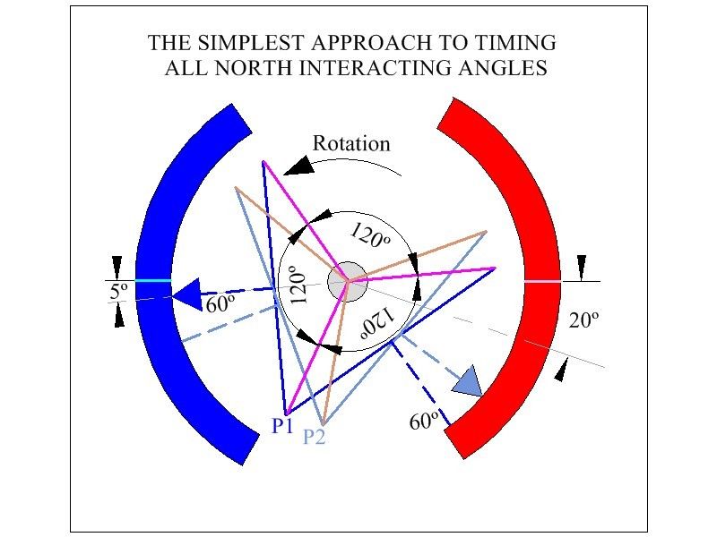 [/IMG]
FOR THE REST, I DID NOT MENTIONED ON DIAGRAM ABOUT THIS BEING FOUR POLES PAIRS ONLY!!...SO ANGLES DOES NOT APPLY "TO ALL" ASYMMETRIC MACHINES...I will fix it tomorrow.
I drew the MagentaGoldLast edited by Ufopolitics; 04-12-2015, 12:57 AM.Leave a comment:
-
Wedges Part #
Hey Garry, sure friend!Originally posted by GChilders View Post
The EIS Part# is WGEDMD20-16-11
Sorry about giving the size in mm previously, I measure them myself, I love metric rather than U.S System...EIS have them in inches though, that is why you couldn't find it...
Wish the best in your coming tests!
Regards
UfopoliticsLeave a comment:


Leave a comment: