This forum is preserved as a permanent archive. The community continues at eMedia Press.

Announcement

Collapse
No announcement yet.

Radiant Collector

Collapse
X
 
  • Filter
  • Time
  • Show
Clear All
new posts

  • vidbid
    replied
    Originally posted by zilano
    Well Sergey!

    u can use the hv terminal of tesla coil to the outer enevelope of cap and charge cap with diodes from ground and then use use it to spark the trafo u can get hot electricity.

    polarization occurs using cap so use an inductor coil after the cap to make it unpolarized and then rectify it and use it to drive trafo.

    rgds

    zzzz
    So we need an updated schematic.

    Leave a comment:


  • vidbid
    replied
    On the Question of What is a Diode-Free Flyback Transformer

    Originally posted by zilano
    the color tv flybacks/monitor flybacks these days have inbuilt diode before hv terminal(black terminal).

    older tv flybacks that is early color models or black and white tv's have flybacks with no diodes attached before hv out. and these can be used for avramenko plug making. from ac hv terminal.

    rgds

    zzzz


    Image courtesy of Zilano

    Leave a comment:


  • vidbid
    replied
    On Kapanadze

    Originally posted by zilano


    well kapanadze used avramenko for initial start. the start device is triggered with diode free flyback trafo. the output of tesla coil is capacitored with one plate going to tesla hv and one to the rectifier ac point. the other ac point of rectifier was grounded. + and -ve then taken from bridge to drive inverting circuit. thats how kapanadze did it. u can do same way.

    post a bigger picture so i can decipher ur ciruit. more better.

    rgds

    zzzz
    I believe what Zilano is referring to when she says a "diode free flyback trafo" is a "diode-free flyback transformer." If that's what she means, well, I had no idea that some flybacks had diodes in them. I'll have to do some research on that.
    Last edited by vidbid; 04-27-2012, 08:09 PM.

    Leave a comment:


  • vidbid
    replied
    Diode Recovery Times

    Originally posted by JohnStone View Post
    Sorry, I have to correct!
    The recovery time of a diode is in fact the switch delay time.

    - A 100ns diode will refuse any action at 10 MHz (conforms to 100ns full periode).

    - A diode is supposed to act in the half periode of an AC signal only. It will refuse therefore any action at 5 MHz (conforms to 100ns as half periode) as well.

    - Any recovery time obove 1/4 frequency periode shall be avoided - in any case!!!! So we have the absolute limit of 2.5 MHz for this 100ns diode. But this is not recommended at all. If we make use of this condition we have built an AC dimmer with phase control.

    - For estimation: I would suggest to convert the recovery time to frequency (1/x) and divide it by more than 8 (12 recommended). Then you have a viable operation frequency.
    Given: 100ns1.25 ..... 0.833 MHz20ns diodes being able to handle about 5 MHz but do not head for higher frequencies. You very probably will not get components within your financial limits - HV, high amp, supoer ultra fast......

    - For your better imagination see this diagram[/URL] and let the recovery time be less than Pi/4 (corresponds to factor 8 above).

    - Please do not hesitate to look in the data sheets. If you do not find a recovery time there then regard the diode to be built for mains frequency only!!!

    - Example: UF 5408 -> recovery time typical 75 ns @ 1A. If you apply max. current it will get slower. Same UF4007. So please calculate these diodes to have 100ns recovey time.

    Please regard the hints above. I want your setups to succeed. Any weak part of a chain detemines the max. load!
    rgds John
    Originally posted by dragon View Post
    I stand corrected...

    Thanks John, that clears the fuzzyness in my mind and a few questions I had in this area -
    Originally posted by zilano
    the aim of showing stealing electricity was just to make forum members and guests to understand that we need high frequency in tandem with high voltage to harvest more power using silicon fast acting diodes. and do the practical also for those who havent made slayer xciter circuit or mini or standard tesla coil.

    the experiment was basic step to understand frequency and voltage effects on charging cap.

    yes we r on same track tesla moray don smith and kapanadze.

    rgds

    zzzz

    Originally posted by JohnStone View Post
    Hi Zilano,
    thanks for your consecutive teaching! It refreshs the forum and oir minds again and again.

    I agree using fast diodes, as fast we can afford. In this sense the component mentioned before seems to be quite desirable.

    15STH06FP


    Interesting posts on this subject.
    Last edited by vidbid; 04-27-2012, 07:17 PM. Reason: Additional

    Leave a comment:


  • vidbid
    started a topic Radiant Collector

    Radiant Collector

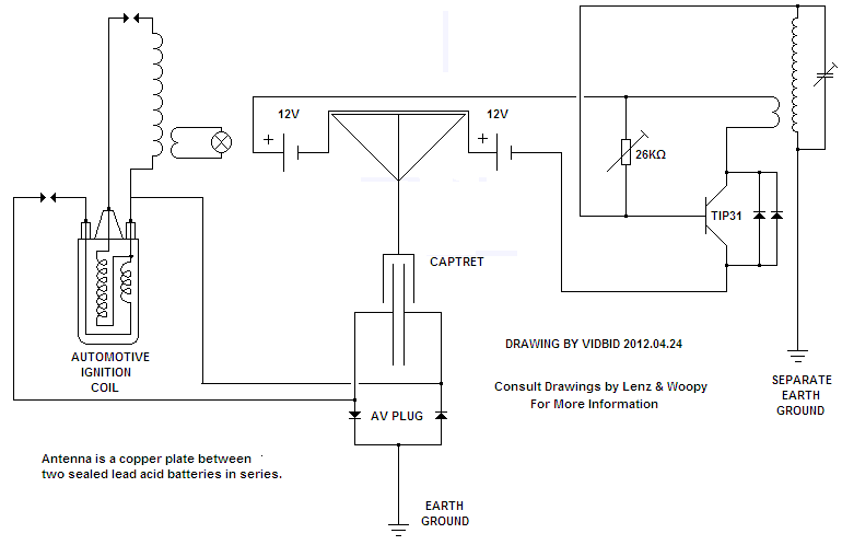
    One could say that there are two circuits at play here. The radiant collector and the radiant exciter.


    The radiant exciter has the purpose of radiantly exciting the batteries, of which there are two.


    The circuit is called a Brovin Kacher Radiant Exciter.

    The circuit for the radiant collector is called a Tesla Radiant Collector.


    Basic Schematic:


    The input to the radiant exciter circuit is about 20mA; however, the radiant collector is not directly connected to the batteries. Output from the radiant collector circuit can be seen to be considerably more than the input to the exciter circuit.

    More Detailed


    Replication #1
    HTML Code:
    http://youtu.be/2JxunfyhtFI


    Replication #2

    HTML Code:
    http://youtu.be/vnHTtpPvsTQ


    Replication #3

    Diodes for Replication #3
    Originally posted by kajunkreations View Post
    15kv 4 amp 100ns.
    HTML Code:
    http://youtu.be/nhbtOvNLnko
    These diodes cost about $30US each.
    Last edited by vidbid; 03-21-2016, 05:16 AM. Reason: Clarification
Working...
X