Announcement

Collapse
No announcement yet.

Charge conserving Capacitive Spring.

Collapse
X
 
  • Filter
  • Time
  • Show
Clear All
new posts

  • #46
    Originally posted by Jbignes5 View Post
    Ok there is a big difference in a single variable cap and twin ones. One would be harmonic(twin) and the other non harmonic(single). The harmonic one would be like putting a teeter tawter in the system and the other would be like jacking the one side up. The harmonic one would be the less leaky since it would have an increase with the associated decrease on the other side. This would make it more powerful as well and you wont have to have extreme high voltages like you are talking then.
    On the subject of leakage you could always shield any wires with static shielding(not connected to anything) This would reflect the leaks back to the source of the leak and contain it better especially if you stay with higher voltages. Cheap static shielding would be a heavy aluminum foil tape or just foil glued onto the wires. If you do them in bands and overlap the bands it should make an effective static shielding for your high voltage app..
    Also drop by our thread in the "don't kill dipole" I am working on the same kind of system to get an ac output with a high voltage pair of leyden jars type setup with twin variable caps on a motorized rotor. Weather or not this will work it would be nice to have your setup to compare to as well.
    I agree with the difference and utility of using two variable capacitors. What I was initially trying to get across is the barriers of understanding in "action reaction separation" and the concept that the time constants dictated by the load impedance and capacitance at a point in time (involves differential and integral calculus to calculate) and how this affects your maximum attainable frequency.

    For example, with a resistive load, you may have a time constant of 1 second. This means in 5 seconds you would have moved 99 percent of the available movable charge.

    However within the first second 63% of the charge is moved. During the remaining 4 seconds only 36% of charge moves. Therefore, your time constants might dictate an operational frequency of X, but in reality you will accomplish more work per unit time if you reduce your frequency 80% or 1/5th of what it was.

    Frequency also must be taken into consideration with respect to how fast you can switch the capacitance. if you can only do it a few thousand times per second, and you are in the PicoFarad range, you are not going anywhere fast.

    I will perhaps show a video soon showing how to find the ionization time of fluorescent tubes, as this is my frequency limiting factor.

    Comment


    • #47
      Originally posted by Armagdn03 View Post
      I agree with the difference and utility of using two variable capacitors. What I was initially trying to get across is the barriers of understanding in "action reaction separation" and the concept that the time constants dictated by the load impedance and capacitance at a point in time (involves differential and integral calculus to calculate) and how this affects your maximum attainable frequency.

      For example, with a resistive load, you may have a time constant of 1 second. This means in 5 seconds you would have moved 99 percent of the available movable charge.

      However within the first second 63% of the charge is moved. During the remaining 4 seconds only 36% of charge moves. Therefore, your time constants might dictate an operational frequency of X, but in reality you will accomplish more work per unit time if you reduce your frequency 80% or 1/5th of what it was.

      Frequency also must be taken into consideration with respect to how fast you can switch the capacitance. if you can only do it a few thousand times per second, and you are in the PicoFarad range, you are not going anywhere fast.

      I will perhaps show a video soon showing how to find the ionization time of fluorescent tubes, as this is my frequency limiting factor.
      What about ultra caps? They can store and discharge even faster and really since Wimshursts machines are just caps that are variable you get the same effect. The trick would be to increase the dielectric value and lessen the gap to increase the capacity ratings. Vacuum does a good job and so will oils that are reduced by boiling to expunge contaminants. Although boiling of the oil will raise the viscosity I'm sure disk design would help in getting the blades to move through the oil very effectively.

      You do have a point about charge response and that needs to be looked at more closely. As to reducing the frequency of the switching of the variable cap you make sense but that only will increase the resistive reactance of the cap. Meaning that the longer the charge stays in the cap the more self discharge that would happen increasing the loss.

      Anyways my system should employ twin variable caps that will only have to variate 120-160v back and forth. This might allow a lower operating base voltage to apply the swing to but I have not built a test rig yet. I want to stay in the high range for voltage but we will see what static like voltages when applied to a variable capacitor will do.

      Using a vacuum does present a problem of maintaining that vacuum but that might be workable. Using oil is a simpler method but might be harder to turn. I'll have to see for myself i guess...

      Tesla did make an open ended tube on one of his devices and could maintain a vacuum with that method I'll have to research that more to see if it is possible to use that method.

      Comment


      • #48
        Originally posted by Jbignes5 View Post
        What about ultra caps? They can store and discharge even faster and really since Wimshursts machines are just caps that are variable you get the same effect. The trick would be to increase the dielectric value and lessen the gap to increase the capacity ratings. Vacuum does a good job and so will oils that are reduced by boiling to expunge contaminants. Although boiling of the oil will raise the viscosity I'm sure disk design would help in getting the blades to move through the oil very effectively.

        Agreed, however I would need a very large and fast Wimshursts for what I want. but as a method of attack not a bad idea for people to peruse....one disk can control 2 capacitors very easily......."Testatika" ???

        You do have a point about charge response and that needs to be looked at more closely. As to reducing the frequency of the switching of the variable cap you make sense but that only will increase the resistive reactance of the cap. Meaning that the longer the charge stays in the cap the more self discharge that would happen increasing the loss.

        I think you misunderstood me, I was pointing to increasing frequency, by using only 1 time constant vs 5, thus decreasing the reactance, besides this it also moves more coulombs per second. My wording was poor now that I look at it "my bad".

        Anyways my system should employ twin variable caps that will only have to variate 120-160v back and forth. This might allow a lower operating base voltage to apply the swing to but I have not built a test rig yet. I want to stay in the high range for voltage but we will see what static like voltages when applied to a variable capacitor will do.

        Look forward to your results!

        Using a vacuum does present a problem of maintaining that vacuum but that might be workable. Using oil is a simpler method but might be harder to turn. I'll have to see for myself i guess...

        these are a few of the reasons i do not want a mechanical method, besides my lack of fabrication ability, it is just overall more difficult.

        Tesla did make an open ended tube on one of his devices and could maintain a vacuum with that method I'll have to research that more to see if it is possible to use that method.


        This was a clever way to draw a vacuum with HV, but i cannot say if this is any more effective than a vacuum pump. I opened up a CRT analogue o-scope the other day, the the cathode ray tube still had a perfect seal and negative internal pressure and it was over 35 years old, so perhaps with quality manufacturing this is not a problem, but like I said before, i don't have the tools!!!

        My response is in red. This is obvious, but it is making me type some sort of a 10 character plus message besides the quote to submit this post, lol.
        Last edited by Armagdn03; 10-20-2010, 08:26 PM.

        Comment


        • #49
          Hello all,

          Progress has been made in this area although a bit slow. I have a good friend who is helping with an incredible driving circuit, for this very device.

          However, what I want to post, and what other people can use, for many parametric purposes, is this modification I have designed based on the Hiddink Patent mentioned earlier in the thread, and alluded to as the preferred method.

          you have two caps, 4 sets of plates, inner and outer. If you remove the inner plates, you have much much less capacitance, because the remaining capacitor is dictated by the two outer plates. But how to physically remove the inner plates????

          With a modified version of:

          Capacity Changer

          Why not add and remove a virtual plate. This of course throws out all of the "force on plates" mumbo jumbo, but that was still important to realize the mechanism in its simplest embodiment.
          So, the problem with the patent as it stands, is that there needs to be a complicated switching scheme to remove completely one of the sources of power. The patent actually dictates two separate power sources!

          Well among the many people I have talked to who have replicated this, (Dr. Stiffler has videos of his replication I believe), the switching has always been the problem with bringing this patent to realization.

          Well, there is a solution!

          YouTube - Solid State Capacity switching Tube 2

          If a person could build a circuit which operates around one of the large capacitance jumps (correlated to the phase changes of the particles in the tube) then you have an easy capacity switching device, to run all sorts of parametric circuits.
          Last edited by Armagdn03; 04-19-2011, 07:14 PM.

          Comment


          • #50
            testing connection,

            Comment


            • #51
              Andrew,

              I am impressed with your line of thought on this thread. I am very certain that you laid a golden egg on the forum.

              I completely see where the use of the middle wire capacitance component was killing the charge in mario's system.

              The conversation between Jbignes5 and yourself easily conveys the idea behind Chris Carson's device. His Device was operating on a negative phase shift where each capacitance was on the opposite half cycle producing an AC signal of "energy synthesis" from the dielectric field.

              Thanks for pointing me to this thread. You are certainly looking at things clearly.

              Dave

              Comment


              • #52
                opposite half cycle AC energy synthesis

                Originally posted by Web000x View Post
                the idea behind Chris Carson's device. His Device was operating on a negative phase shift where each capacitance was on the opposite half cycle producing an AC signal of "energy synthesis" from the dielectric field.
                Dave,

                Would you mind elaborating on that?

                Are you talking about the potential difference between two negatives
                that alternate?
                Sincerely,
                Aaron Murakami

                Books & Videos https://emediapress.com
                Conference http://energyscienceconference.com
                RPX & MWO http://vril.io

                Comment


                • #53
                  Originally posted by Aaron View Post
                  Dave,

                  Would you mind elaborating on that?

                  Are you talking about the potential difference between two negatives
                  that alternate?
                  Sure,

                  Eric Dollard mentioned the importance of inductance/capacitance parameter variation with respect to time for the "synthesis of energy". In Mr. Dollard's book titled "Symbolic Representation of the Generalized Wave", Read Pg 57 where at the bottom of the page it lists the quantity called -HB; H is receptance or negative resistance, and B = mhos in farads per second.

                  That quantity suggests energy production from the dielectric field by a varying capacity. I have yet to verify this experimentally, but this idea is due to standing on the shoulders of giants if you will.

                  Armagdn03 spoke about the exchange of charge between a dielectric parameter variation which stood the test of equations for realistic and theoretical application.

                  Peter L Quote:
                  The sixth picture shows another, lower angle shot of the whole machine. It also shows how one section is out of phase with the other.
                  If you were to have two capacitors that vary out of phase like Chris Carson had, you would have a setup that could move a maximum amount of charge by the equation Ψ=eC (Ψ = Total Dielectric Induction in Coulomb, e = electrostatic potential in Volts, and C = Capacitance in Farads) between capacitor plates. The displacement current due to the potential differences can then run through a load while the capacitors are moving towards equilibrium. From my understanding, the Ψ=eC stays in balance.

                  Armagdn03's description of using conservation of charge (variable capacitance) vs. time manipulation has me convinced you can indeed change the energy of a system and collect a bit extra.

                  Dave
                  Last edited by Web000x; 12-12-2011, 03:37 AM.

                  Comment


                  • #54
                    Originally posted by Web000x View Post
                    Andrew,

                    I am impressed with your line of thought on this thread. I am very certain that you laid a golden egg on the forum.

                    I completely see where the use of the middle wire capacitance component was killing the charge in mario's system.

                    The conversation between Jbignes5 and yourself easily conveys the idea behind Chris Carson's device. His Device was operating on a negative phase shift where each capacitance was on the opposite half cycle producing an AC signal of "energy synthesis" from the dielectric field.

                    Thanks for pointing me to this thread. You are certainly looking at things clearly.

                    Dave
                    Thank you!

                    I also gave one really great solution to the switching problem encountered with the Hidink patent a couple posts back. There was the need for complicated switching schemes, which no longer exist with the method of accomplishment I showed. This device is in itself over-unity. I know personally of at least one person who has this down pat however out of respect to the original inventor, (which may still be alive) he has kept quiet.

                    Chris Carsons device was a super simple demonstration, but a mechanical implementation for energy production on that scale is a little silly when you consider the limitations of the system! 10,000 rpm on a spinning multi plate cap??? Wow talk about model building difficulty. Using phase changes of ionized gas, OR using uv light to excite a layer of phosphorus as depicted in these patents.


                    http://www.google.com/patents?id=zMI...page&q&f=false

                    http://www.google.com/patents?id=nvs...page&q&f=false

                    Keep in mind for this system the critical parameters for power generation.

                    1)Capacitance of the capacitors (total charge held)
                    2)Starting voltage across caps (Total charge held)
                    3)Impedance of the load (Time constants, dictates coulombs per second or watts)
                    4)Switching speed (directly related to time constants)
                    5)Limit on how quickly one can switch between between conductive plasma phase and non conductive phase. User Tecstatic has released some information on this in the private part of Heretical builders forum, and I will ask permission to re post here.

                    Comment


                    • #55
                      For those who enjoy the work of Eric Dollard this is a direct application of his theory. I will be posting with reference to four quadrant theory for a bit, but am a bit predisposed at the moment.

                      Comment


                      • #56
                        Great thread, thanks for pointing me at it.

                        The two google patent links you just posted are 404. Can you re link them?

                        Also, which one is the hidink patent you mentioned?

                        I like the line of thought about using plasma tubes to control the switching, but I'm not clear on what that would look like. I have spent a lot of time studying the schematic of the voltage converter Eric uses in his car and trying to understand how I could create a solid state embodiment of that, but all the ideas I came up with are far too complex. Using plasma tubes is a great suggestion.

                        What kind of tubes are available? Would transient voltage suppressors be suitable at all? I have had a difficult time designing a circuit that uses them in a manner similar to how don smith uses them, but I have not spent too much time trying.

                        Comment


                        • #57
                          Originally posted by 7imix View Post
                          Great thread, thanks for pointing me at it.

                          The two google patent links you just posted are 404. Can you re link them?

                          Also, which one is the hidink patent you mentioned?

                          I like the line of thought about using plasma tubes to control the switching, but I'm not clear on what that would look like. I have spent a lot of time studying the schematic of the voltage converter Eric uses in his car and trying to understand how I could create a solid state embodiment of that, but all the ideas I came up with are far too complex. Using plasma tubes is a great suggestion.

                          What kind of tubes are available? Would transient voltage suppressors be suitable at all? I have had a difficult time designing a circuit that uses them in a manner similar to how don smith uses them, but I have not spent too much time trying.
                          Here are the patents your after;
                          Louis O'Hare Patent 1

                          Louis O'Hare Patent 2

                          Joseph Hiddink

                          Also just a note on Dollard's voltage converter. It may have been modified from that schematic I posted a while back since logic tells us that it will loose charge in the same way as Mario's device did earlier in the topic. I don't question any of his work in any way shape or form but I don't think this device is worth bothering about too much for reasons Andrew posted earlier. I had a friend replicate the circuit solid state and he said that it operated in just the same way as a boost converter does and was quite inefficient.

                          I don't wish to deter you from your study but I thought I'd put that out there.

                          Raui
                          Scribd account; http://www.scribd.com/raui

                          Comment


                          • #58
                            Yes, I am aware that the voltage converter is a common device and does not produce large amounts of excess energy... But I still want to study it so I understand how it works and can build something like it. This thread is helping with that a lot.

                            Also, there has to be SOME reason Dollard talks about this device. I would like to know what it is he is trying to teach us by talking about it.

                            When I build "normal" electrical devices, any misconceptions I may have about theory are easily dispelled since I get direct experience with measuring the device.

                            I am very curious if there is a good way to use transistors to charge capacitors in parallel and discharge in series, or vice versa. What I came up with seems horribly complicated. I have not been able to find any schematics or even learn about any common devices that do this.

                            Comment


                            • #59
                              Originally posted by Armagdn03 View Post
                              I also gave one really great solution to the switching problem encountered with the Hidink patent a couple posts back. There was the need for complicated switching schemes, which no longer exist with the method of accomplishment I showed. This device is in itself over-unity. I know personally of at least one person who has this down pat however out of respect to the original inventor, (which may still be alive) he has kept quiet.
                              I personally have contacted Joseph Hiddink. Facebook! He's alive and well, but VERY saddened and obsessed with his discovery/invention because no one (governments, manufacturing, r&d) has taken him seriously and helped him develop it.

                              Aaron, would you think it's ok for me to post his Facebook id? He seems to not be able to accept instant messages, and it sometimes takes him a while to respond to messages, but we have conversed a few times.

                              I really believe that if he saw a great interest in this, he would love to help out.... He does want to develop it commecially, but it's so simple and he doesn't seem to mind, and actually encourages its development.


                              And one more very interesting side note:

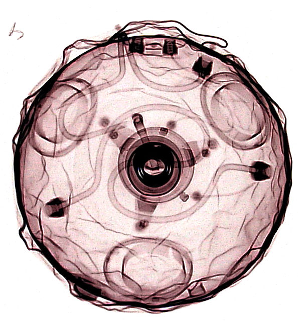
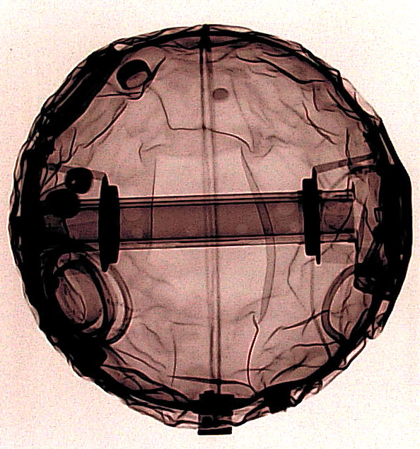
                              RogerArrick.com Roger Arrick Mystery Orb


                              more pictures are on the page

                              A metal sphere was found in a rive and x-rays were taken. It is 2 concentric spheres with a gas discharge tube in the middle surrounded by a metal cylinder. A wire runs to each sphere, the cylinder, and each end of the discharge tube. I've downloaded and backed up these pictures because it's vital PROOF that the government/militarily/machine uses this technology, and poor Joseph doesn't get a dime.

                              That's right, this not only produces high voltage, but the negative pulse has a matter repulsion effect and a positive pulse has an attraction effect.

                              Incase you didn't connect the dots....it's a flying saucer propulsion device

                              Comment


                              • #60
                                and if you think that's weird, it get WAY WAY WAY WEIRDER
                                Tom Swift and his Polar-Ray Dynasphere


                                I was doing a google search and I forget the term I was looking for, but I think I was trying to find out if anyone had made a piezo-electric concentric-spheres-capacitor oscillator out of quartz.

                                Guess what, young Tom Swift did! To power his Polar-Ray

                                from the text:
                                ["Well, as you know, that double-walled crystal sphere at the stern is my electrostatic-field device. I've decided to call the gadget a 'Dynasphere' -- or 'Polar-Ray Dynasphere,']

                                also very weird that Keely invented a thing with that name, but that's completely different. (Or is it?)

                                Tom Swift's 'fictional' device is VERY similar to hiddink's device, yet acting as an osccilator with the medium of the highest Q known (correct me if I'm wrong) QUARTZ

                                And the whole electrostatic field shaping of his electro-propulsion ship is very clear and accurate.

                                Tell me I'm wrong.

                                Comment

                                Working...
                                X