Announcement

Collapse
No announcement yet.

Joulethief SEC exciter and variants

Collapse
X
 
  • Filter
  • Time
  • Show
Clear All
new posts

  • Maybe it's partly because of what happened with the Slayer Exciter, and how when you give your hard work and designs to others, they will use it to make money, and give no credit to the inventor of that circuit.
    Slayer 007 has a youtube channel, if you want to check into what he has going on now.
    Also because wireless RF HV transmission affects all the electronics in ones house, including Tv, radio, and PC, and may not be all that good for you, as well.
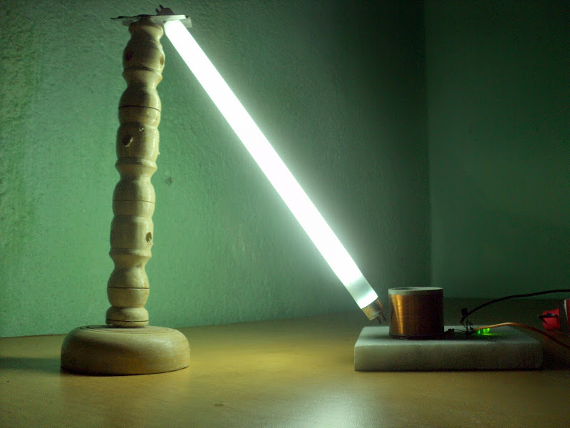
    That is why I suggested connecting by wires both ends of the florescent tubes, or bulbs, to two different oscillators which can be run off of the same input source. Instead of using wireless, as wireless is also limited to only a few feet away from the tubes, at most. Wired Exciters don't have that limitation, and produce the best light output. Normal florescent bulbs are made to run on twin oscillator circuits,in order to obtain their best lighting output.
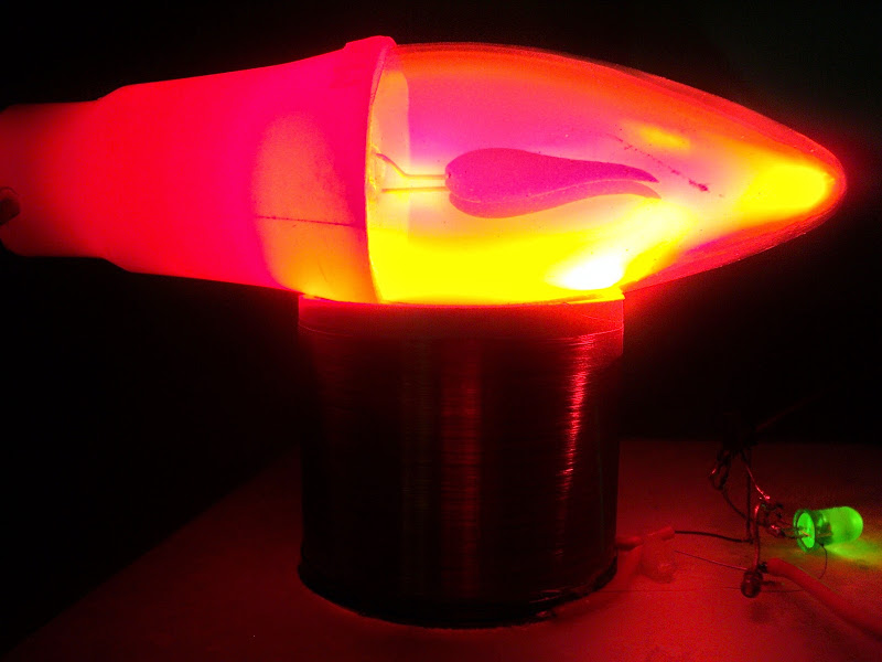
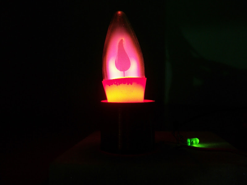
    Led bulbs are different, though, and don't need twin oscillators to perform well.
    Nick_Z

    Comment


    • Hello guys! Wake up

      How are you? Long time no see!

      Well summer is here and so back are the coil experiments. Here is my 30mm tiny fat exciter running with only three components. It's small but is no less powerful than the large ones. It runs from 3V up to about 12V before the transistor needs heatsink. The whole setup is done on a 12cm x 12cm piece of white marble stone piece.

      Parts used- BC547 x1, 100K x1, Green LED x1

      Secondary - about 250 turns of hair-thin enameled wire; no top load.
      Primary - 6 turns of SWG24 enameled wire about 1mm below the secondary coil; wound over the same pipe.
      Tuning - none.

      A video is being cooked, meanwhile, some pix- (Matchstick for scale)


      Cheers.
      shaan

      Comment


      • And here it is...

        Tiny 30mm Slayer Exciter @9V - YouTube

        cheers
        shaan

        Comment


        • Shaan,
          I'm impressed with the simplicity of your setup.
          I'm wondering - do you think there's any way to build this kind of exciter without a transistor? This is something I'd be interested in. I saw one guy, I think his name is Alejandro [in Spanish] on YT using two DC motors and a reed switch. Any thoughts?

          Maybe I should start a separate thread for this, as it's no longer a JT or JT variant without a transistor, is it?
          Bob

          Comment


          • Hi Bob.

            Nice to see some are still awake in this thread.

            A resonant system like the slayer exciter needs a switch. Any kind of switch that can run at the coils' natural resonance frequency should be able to make the 'thing' happen. The small signal transistor I used can switch happily at hundreds of megahertz and wastes minuscule amount of energy as heat. I think there is some form of soft switching happening in the system, like in a ZVS/ZCS system, and if it is true, then I doubt it will work efficiently with a motor switch, if at all.

            All the best.
            shaan

            Comment


            • Thanks for the explanation, Shaan. Yes, still awake Friday afternoon post-work week coffee keeping the eyes open. I guess it comes down to what can provide a high enough frequency, and the transistor is probably the only if not most practical way.
              Regards,
              Bob

              Comment


              • Awesome

                Hi shann, That is very cool. I know nothing about this thread but that looks very easy to replicate .
                Do you need the marble , or is that optional?
                Also that flourescent tube , is the top attached to anything?
                I have a bunch of different transistors ( all salvaged) maybe I have one that will work. One last Q ; do you need the led in there?
                Awesome , thanks for the share.
                artv

                Comment


                • Originally posted by shylo View Post
                  Hi shann, That is very cool.
                  Thanks. Welcome to the Exciter thread.

                  I know nothing about this thread but that looks very easy to replicate .
                  Do you need the marble , or is that optional?
                  Yes indeed it is very easy to replicate. You don't need the marble. It's purpose is to make the whole thing look good and a solid plus portable base.

                  Also that flourescent tube , is the top attached to anything?
                  Yes. A wooden holder with no electrical connection to the tube.

                  I have a bunch of different transistors ( all salvaged) maybe I have one that will work.
                  Rough guess- most will.

                  One last Q ; do you need the led in there?
                  Yup. One can use diodes too. I used LEDs as it serves as an 'on' indicator while feeding the transistor the signal from the secondary in order to start and sustain the oscillation.

                  Cheers.
                  shaan

                  Comment


                  • There are many different plasma propulsion concepts.
                    And because of experimenters like you we can
                    watch videos and categorically compare various ideas.

                    slayer exciter experiment
                    https://www.youtube.com/watch?v=NgdJV3ZT1nk

                    The velocity builds up slowly
                    https://youtu.be/N6lPlyMUtf4?t=59

                    NASA Ion thruster
                    https://www.youtube.com/watch?v=HcEc7dnRppw

                    So what is plasma re-deposition ?
                    https://www.youtube.com/watch?v=03CuKjrMIMg
                    Last edited by mikrovolt; 05-22-2017, 02:55 AM.

                    Comment


                    • Best thread I've read so far guys and gals. Some amazing stuff. I tried a fugi trigger coil with 5+5 turns on a teeny toroid. Barely got av led action so I swapped out the trigger tranny for a 4 pin fuji tranny and got a little bit more action. Water is fun to play with. curious that a 4watt led mains globe with Edison terminals glows dimly when the tip or centre terminal is dipped and remains so when further submersed wetting both terminals. My neon goes out when both leads are dipped. i can see how these things can be addictive. Kinda strange this thread has stalled. Anyway good work by all before me.
                      Cheers.
                      Attached Files

                      Comment


                      • Here is a rewound choke with several hundred turns of .3 mm magnet wire and 2 turns for a primary. At 3.7 v reg. With the attached circuit it is the strongest field I have seen so far, including some 12v runs. T1 is a tip 122,led1 is a bright white that doesn’t light, but still functions normally on 2.32-4.5 v dc, go figure, led2 is a dim red, c1 is 3kv 10 nf. It runs at 50 kHz.
                        — turns out there are similar kits on eBay now. Last pic. Under $4 on the slow boat from China.
                        15KV High Voltage Generator Step-up Inverter Arc Ignition Coil Module DIY Kits https://www.ebay.com.au/i/162670719183
                        Attached Files
                        Last edited by voltan; 10-15-2017, 01:16 AM.

                        Comment


                        • Here’s my first module assembled and running. The 3 holes in the pcb for B C E needed some enlargement and the holes for the diode and resistor were closer together than neat, but it fired up first go.
                          Nice to have a floating/isolated secondary coil,instead of having high voltage in the whole circuit.
                          I’m thinking UV/safety glasses might be a good idea when xenon flash tubes are run like this.As the tube gets warm to hot.
                          I added a fast recovery diode, in pic2. This sends a pulse of charging energy back into the source right after T1 switches off and the coils field collapses. The modules peak output voltage is reduced, but the xenon tube still has a steady thin arc. I have also added a low esr cap and a 1 k variable pot. To the original circuit. The cap presumably absorbs the charging pulses a bit better than a battery source would take rapid reversals. The pot Gives it adjustable output,frequency and can allow for a higher input voltage and control T1’s temp. The supplied heatsink gets hot to touch in short time. I’m waiting on a 5A panel meter to compare input and return. Ok 2 amps input and 610 ma return. It runs at 99 — 189 kHz with loads and mods I have tried so far.
                          Looks like the secondary coil has to be potted/hot waxed or siliconed for best performance and to avoid premature failure due to arcing. The module should run silently. If it squeals, shut it down immediately and seal up the secondary coil. The core splits easily. Pic 3. The primary side has about 30 turns driven and about 35 turns for feedback. Will try 5/6 turns with a well sealed sec coil.
                          Cheers
                          Attached Files
                          Last edited by voltan; 11-11-2017, 11:59 AM.

                          Comment


                          • Lidmotor's working out part of the Dr. Stiffler diode loop.

                            https://youtu.be/F7zBvOEJSP4

                            Slider working on resonance

                            https://youtu.be/2euJ7vGNkjk

                            Adjust the (SG) signal generator on the Stiffler loop then measure light in a light box, let's say 500 lumens
                            Using DC constant current set 60 % rated for example. The light box measures 500 lumens. record the voltage and milliamps.
                            We find the value to be 680 mW for example
                            It is possible to measure output of RF watts out of the SG using a standard dummy load.
                            instead of DC we are using SG using RF dialing in for 500 lumens measurement in the light box.
                            If led running on DC equals 100 percent then what percent is the Stiffler led diode running on RF ?
                            Last edited by mikrovolt; 05-31-2018, 06:20 AM.

                            Comment

                            Working...
                            X