Announcement

Collapse
No announcement yet.

Donald Smith Devices too good to be true

Collapse
X
 
  • Filter
  • Time
  • Show
Clear All
new posts

  • Perreault Plasma Valve Stage 1 Disclosure

    Originally posted by Wistiti View Post
    Steel and aluminum bolts for the PPV .

    I just wanted to say thank you to tswift, Mwtj and Serendipitor for keeping the PPV details a secret.

    I know this next move will be appreciated as they won't have to conceal any part of the device from anyone.

    I won't have to photoshop any pictures either.

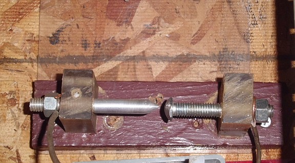
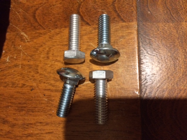
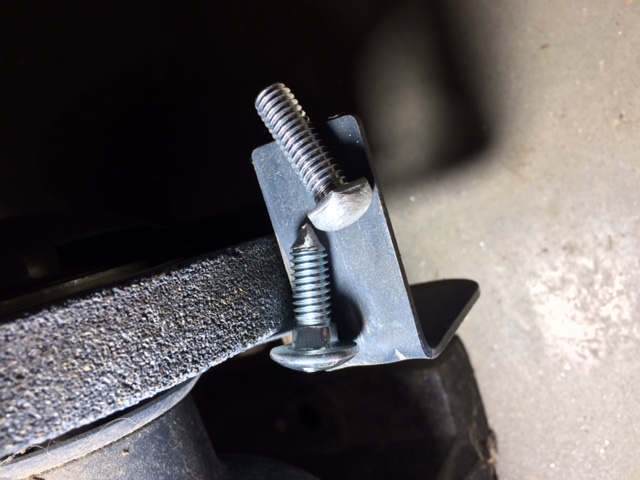
    I present to you the Perreault Plasma Valve Stage 1

    These pictures are courtesy of tswift & Serendipitor:


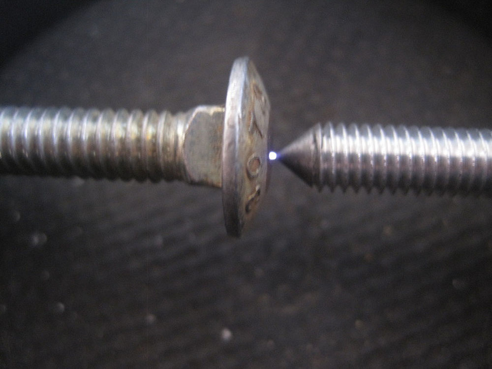
    The anode should be made from aluminum.

    The cathode should be made from iron. (Steel is close enough)


    However, there is a little twist in the story

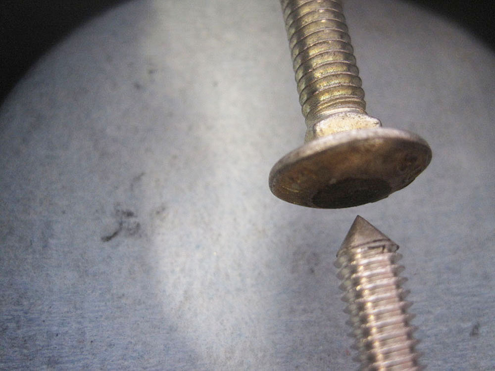
    The most efficient PPV Stage 1 can be made by having a domed anode and a pin point cathode!

    So opposite of what is shown in the pictures.


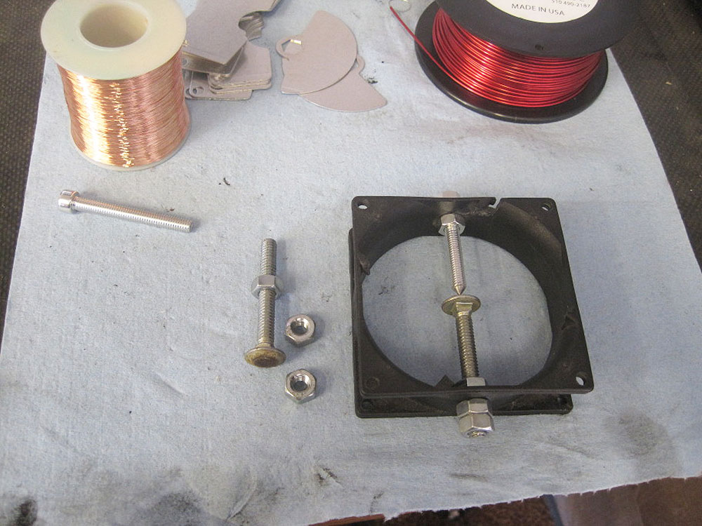
    If you have access to a lathe then I'm sure you can make a better dome.

    The finer the threads the more adjustable your PPV will be.


    Not many inventors get to invent there own electrical components and symbols.
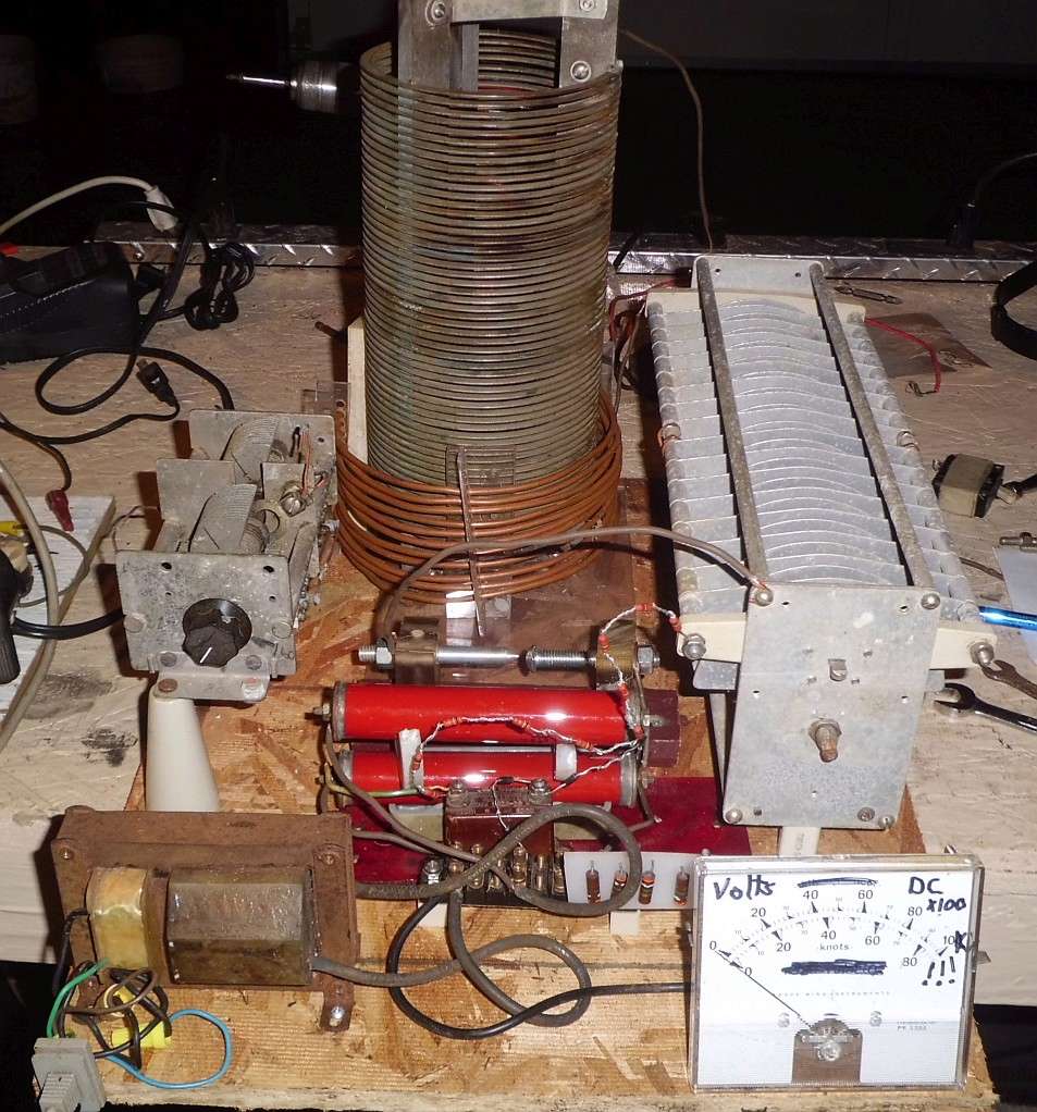


    What is a PPV?

    It is an ultra high frequency, high voltage, plasma diode. It is the key component that will allow you to tap the endless sea of ions for your electrical needs.

    Moray used radioactive material to break down the gap resistance. The PPV uses dissimilar metals to do the same thing.
    Last edited by soundiceuk; 01-12-2017, 11:18 PM.

    Comment


    • Now we can talk about this publicly tswift.


      "I was amazed how big a difference in the coil ringing the PPV made! Now the waveform is very little transient and almost all clean ringing at the resonant frequency. I'm guessing with the antenna attached and tuned, the waveform will be virtually a steady-state sine wave."

      Have you measured to see if your findings were correct?

      Comment


      • Originally posted by serendipitor View Post
        But I must say that having bright shiny copper for the antenna is a tall order, in this rainy climate. All my wire antennas get a surface corrosion over time. I'll clean up the wire initially, but it will not stay that way.

        Tesla talked about polishing the surface of his plate collectors as well.
        Oxidized bare copper wire has rectifying ability.

        Apparently Moray used this for an antenna too.

        Rain increases the amount of ions available.
        Last edited by soundiceuk; 01-11-2017, 11:25 AM.

        Comment


        • Originally posted by soundiceuk View Post
          The earth ground is definitely important. Hence why Tesla used a 300ft deep earth over an aquifer for Wardenclyffe.

          Yes, this is very exotic and unachievable by 99.9999999% of people.

          You just have to do your best, based on your funds.

          An 8ft deep dedicated ground rod is most probably going to be a basic necessity.


          Thank you very much

          Comment


          • Originally posted by soundiceuk View Post
            Now we can talk about this publicly tswift.

            "I was amazed how big a difference in the coil ringing the PPV made! Now the waveform is very little transient and almost all clean ringing at the resonant frequency. I'm guessing with the antenna attached and tuned, the waveform will be virtually a steady-state sine wave."

            Have you measured to see if your findings were correct?
            So glad you guys decided to release this! Combined with the information in the download e-book and this thread, this is now a complete public release of a stage 1 type device. I hope everyone realizes how important this is, it can now be replicated around the world, at least by those skilled enough in electronics. I think it is likely to be unstoppable now.

            Now that I have a working HV supply I will try it attached to the antenna later today! Hope to have more test results soon. I also invested in a true 100x HV oscilloscope probe with 5kv capability so I can do better measurements on live circuits.

            Back when I sent this to soundiceuk originally, I was driving the primary with the PVM12 directly as you would a Tesla coil. Using a regular spark gap instead of the PPV will make the coil oscillate of course, but I found that once I changed the anode to the aluminum point that it worked much better, with less transient and much cleaner ringing.

            Comment


            • Originally posted by tswift View Post
              So glad you guys decided to release this! Combined with the information in the download e-book and this thread, this is now a complete public release of a stage 1 type device. I hope everyone realizes how important this is, it can now be replicated around the world, at least by those skilled enough in electronics. I think it is likely to be unstoppable now.

              Now that I have a working HV supply I will try it attached to the antenna later today! Hope to have more test results soon. I also invested in a true 100x HV oscilloscope probe with 5kv capability so I can do better measurements on live circuits.

              Back when I sent this to soundiceuk originally, I was driving the primary with the PVM12 directly as you would a Tesla coil. Using a regular spark gap instead of the PPV will make the coil oscillate of course, but I found that once I changed the anode to the aluminum point that it worked much better, with less transient and much cleaner ringing.


              i have a question about the effectiveness of PPV in high voltage high frequency environment, does it really effective in MHZ range frequency precisely around 1 MHZ frequency, the voltage around 40 KV, my work is similar to your work but i am focusing on earth electrons or ground grounding , i need more info about the PPV based on your experiments , thanks in advance

              Comment


              • I would just try it. What's the worst that can happen?

                It beats blowing up expensive HV diodes.

                I wondered what would happen if a PPV was used on a hairpin circuit

                Comment


                • Grinding time!!
                  Attached Files

                  Comment


                  • Originally posted by Wistiti View Post
                    Grinding time!!

                    I would refine the finish with some fine grade 800, 1000, 2000 grit.

                    Polish it if you can afterwards.

                    Sharper the tip the better.
                    Last edited by soundiceuk; 01-11-2017, 11:25 PM.

                    Comment


                    • Originally posted by soundiceuk View Post
                      I would just try it. What's the worst that can happen?

                      It beats blowing up expensive HV diodes.

                      I wondered what would happen if a PPV was used on a hairpin circuit


                      nothing worst will happen i am just asking maybe there's some special recommendation for better performance, it will be part from a special tuning mechanism i hope to success in it !

                      Comment


                      • Originally posted by med.3012 View Post
                        nothing worst will happen i am just asking maybe there's some special recommendation for better performance, it will be part from a special tuning mechanism i hope to success in it !
                        There is a particular reason it is used for 500KHZ STORM FREQUENCY.

                        The whole design purpose of using it, is to convert this natural planetary frequency into standing waves.

                        The primary side is electromagnetic (electrons) and follows ohms law.

                        The secondary side is radioionic (ions) and ohms law is reversed.

                        It wasn't designed to do anything else.

                        I'm still waiting for the first replicator to show a bulb/s shorted and still running to show it is low voltage / high frequency.


                        It will be interesting to see what anomalies anyone finds though.

                        Got to be safer than experimenting with rail guns and exploding wires!

                        Happy experimenting!

                        Comment


                        • Originally posted by soundiceuk View Post
                          There is a particular reason it is used for 500KHZ STORM FREQUENCY.

                          The whole design purpose of using it, is to convert this natural planetary frequency into standing waves.

                          The primary side is electromagnetic (electrons) and follows ohms law.

                          The secondary side is radioionic (ions) and ohms law is reversed.

                          It wasn't designed to do anything else.

                          I'm still waiting for the first replicator to show a bulb/s shorted and still running to show it is low voltage / high frequency.


                          It will be interesting to see what anomalies anyone finds though.

                          Got to be safer than experimenting with rail guns and exploding wires!

                          Happy experimenting!


                          500KHZ and the ability to rectify is enough for me ! thanks

                          Comment


                          • Originally posted by Wistiti View Post
                            Thank you guys for the info on the cap. It is good news!

                            Sorry for that but I have another question... (as I have said before I may have many!! )

                            It is the second time I see a replication using magnet wire on the hv side. (L1-L2) Do these wire are really enough insulate for that??? If so it is another good news cause I have a bunch of them. For how much volt are they be made for? Maybe using these magnet wire with some spacer between the turn to avoid arcing, I think of something like plastic wire from a grass trimmer...
                            This is speculation but we believe Moray kept burning out his valves in the day because he wasn't using HV wire.

                            The ion surges are much greater in the day.

                            Comment


                            • Lots of sparky-sparky, resonance still elusive

                              I had some time to spend testing the device this evening. First I rewound the L2 coil with HV wire, as it was apparent that with the whole L1 coil charged to 12KVDC potential, the wire I was using was not going to insulate against that kind of difference. It looks like I will probably have to make another L1 coil and do it right with HV wire but as a half measure I just did L2.

                              I also used my new HV probe to measure the floating potential on the L2 side circuit and I found that it was at about -3.5KVDC, with a blip every time the PPV fires. This can be seen in the blue scope trace in the picture. Unfortunately, my antenna is not at the same place as my shop building where my electronics workbench is. To test the rig I have to haul the whole thing outdoors and about 100 yards away. To make my life simpler for testing and tuning, I use an antenna simulator so I can power it up in the shop. I don't believe this will give the same effects as the antenna will, but it will make the PPV fire and coils ring and can be used to check resonant frequencies and proper operation of the circuit. Now that I stocked up on some HV resistors, I use a 100M resistor to ground from the connection where the antenna would go. This gives a firing rate of about 500 Hz on the PPV. There is enough current leakage due to either conductivity in the wood, insulation leakage, or corona that I get just a little sparking in the PPV even with no antenna and no resistor.

                              Since the circuit seemed to be operating properly I hauled it out to the testing location. With the antenna and ground connected I got a strong spark, I didn't bring the scope out but it was audible and sounded similar to when it was on the bench, so several hundred hertz. I tuned C2 up and down slowly and carefully looking for any change but didn't notice anything. I left C2 at the position I tested to be 500 KHz on the bench and tried tuning C3 instead, but likewise nothing. So I brought the test rig back to the shop for further tuning. Somehow it's still far enough out of tune not to be even close, more troubleshooting is needed. Also, I may not get any results at all with the magnet wire coil, it seems that the HV wire really is a must.

                              I'm encouraged that this is a step forward, at least I'm getting good charging voltage now. The static charging effect around the device is noticeable and I get a zap every time disconnecting the battery. The ozone is also significant, in the shop I have to run a fan to help dissipate it.
                              Attached Files

                              Comment


                              • I figured out at least part of the problem. Originally I had designed the L2 secondary as a smaller tube within the L1 primary. I arranged the C3 capacitance for resonance with the measured inductance of the L2 coil done that way, and I never changed it when I swapped L2 for two turns of wire wound around the outside! Silly mistake, it will need much more capacitance to resonance at 500 KHz.

                                Comment

                                Working...
                                X