Announcement

Collapse
No announcement yet.

Donald Smith Devices too good to be true

Collapse
X
 
  • Filter
  • Time
  • Show
Clear All
new posts

  • soundiceuk
    replied
    Originally posted by radioionics View Post
    If my work wasn't constantly being plagiarized, and being disrespected the world would have "free energy" in their hands by now. I refuse to give such a gift to ungrateful people. Because of this there will be a price, it will be around 10 million dollars now for the public to be able to have complete access to the technology. Really, it is a small price to pay these days. I would have given it gratis if I was given credit where it was due.

    -Bruce P.
    Doesn't matter if that's a million people paying 10 dollars or 10 million paying a dollar.

    I know a lot of folk have their own strong opinions on selling a free energy technology.

    Mine has changed many times over the last 7 years.

    Bruce has so much more than this it would be insane for him not to benefit so he can carry on with his research and development of his other technologies that will change our lives forever!!

    A radioionic receiver would fit on your bench and power your entire house.

    Just need 10 million people willing to pay a dollar and it's ours....

    I'm sure I'll probably get flamed in some way for saying this.

    Eventually one of you will make a demo video based on what Bruce has already disclosed and we will find these people willing to contribute.

    Then Bruce hasn't got to bear the burden anymore and we will have the ability to be free and evolve as we should have a very long time ago!
    Leave a comment:


  • tswift
    replied
    Originally posted by Solarlab View Post
    F.Y.I.

    Hi tswift,

    You present some interesting, thought provoking, information and postulation.

    Another approach that you may find of value is found in Vasiliev's "Electricity
    and Unusual Features
    " book of 2015 (attached in a translated .pdf format).

    He attributes the anomalies you mention to the Positron [+], it might be considered
    the opposite, or conjugate, or antiparticle to the Electron [-] and he provides some interesting
    evidence and observations.

    Anyway, have a look...

    FIN
    Thanks, this looks like a very good reference! I'll take the time to digest it thoroughly, may take a while. If he's talking about electron/positron symmetries then we're probably on the same track. Conventional physics recognizes "CPT symmetry", where the laws of physics are identical considering an electron moving to the right in forward time with a positron moving to the left in reverse time. To quote from the wikipedia article:

    The implication of CPT symmetry is that a "mirror-image" of our universe — with all objects having their positions reflected by an arbitrary plane (corresponding to a parity inversion), all momenta reversed (corresponding to a time inversion) and with all matter replaced by antimatter (corresponding to a charge inversion)— would evolve under exactly our physical laws. The CPT transformation turns our universe into its "mirror image" and vice versa. CPT symmetry is recognized to be a fundamental property of physical laws.
    To the best of my knowledge, CPT symmetry is believed to be absolute by current generally accepted physics. However, there are known cases of CP symmetry violation, which implies T symmetry violation. So even to a university-trained physicist, the idea that some particles could be time-reversed is actually not far from what they learned in school. Like I said previously, if an inventor comes forward claiming some magic "radiant energy" machine, most scientists won't even seriously consider it because it isn't framed in language they understand. When that day comes, if there is at least a proposed theory that might be an extension of things they have been taught but doesn't require completely invalidating them, then I think at least the scientific community will find it much more palatable. Perhaps the general public probably won't care as long as it works as advertised, but a lot of people trust experts and people with "PhD" after their name. Right now there is a big intellectual hurdle to overcome where the experts won't even take this kind of work seriously.

    Leave a comment:


  • radioionics
    replied
    Really? Are you serious? Then, you haven't read it carefully. The description clearly shows my work predates the patent in question.

    "Said modification can also be utilized without the use of the radioactive substance 4, if the input source has enough energy to excite the vapor or gas into its electrically conductive state."

    "A simple earth ground and antenna raised to a suitable height can be used to take advantage of the potential difference that exists between the planet and its atmosphere, although this is not always practical. Charging capacitance 9 with this method is unpredictable and slow. Any suitable circuit may be used to supply the required potential difference to energize the alpha-fusion valve 8 and this will not depart from the spirit of the invention." Also, please study figure 2. This is as clear as day!

    In fact, with the use of my unique discharge tube, my patent is much more efficient in converting the atmospheric ions into useful electrical power. My work resides in the "public domain" and can be viewed at RADIOIONICS RESEARCH TEAM, where several creame of the crop replicators are currently reproducing my contributions.

    BTW, FYI, my discharge tube is even more advanced than what I've revealed in my patent, using more effective semiconductors. These have been shared in my Earth Ion Energy forum PPV Discussions. This is now in the public domain and as a result cannot be claimed in a new patent.

    If my work wasn't constantly being plagiarized, and being disrespected the world would have "free energy" in their hands by now. I refuse to give such a gift to ungrateful people. Because of this there will be a price, it will be around 10 million dollars now for the public to be able to have complete access to the technology. Really, it is a small price to pay these days. I would have given it gratis if I was given credit where it was due.

    -Bruce P.


    Originally posted by Solarlab View Post
    F.Y.I.

    Hi Radioionics;

    Your quote "This patent plagiarizes my work. My patent clearly predates it...", if you are referring to patent US9564268B2 https://patents.google.com/patent/US9564268B2/en, then please forgive me but I do not see any relation between your US7800286 and the above???

    Your patent appears to be more related to some of Farnsworth's patents of the late '20s, 1930s and '40s IMHO. (Farnsworth - the inventor of television).

    Also, in studying Farnsworth's work I note some interesting, what might be, references to overunity; for example his US2071516A. I'm finding many of his earlier patents to be quite interesting and informative.

    https://www.google.com/patents/US207...p1DLwQ6AEIIjAA

    Having nearly completed an analysis of the Ruslan, et al, traveling wave approach; the multipaction phenomenon might also be related, and/or a separate method.


    FIN
    Last edited by radioionics; 05-14-2017, 06:30 AM.

    Leave a comment:


  • Solarlab
    replied
    F.Y.I.

    Hi tswift,

    You present some interesting, thought provoking, information and postulation.

    Another approach that you may find of value is found in Vasiliev's "Electricity
    and Unusual Features
    " book of 2015 (attached in a translated .pdf format).

    He attributes the anomalies you mention to the Positron [+], it might be considered
    the opposite, or conjugate, or antiparticle to the Electron [-] and he provides some interesting
    evidence and observations.

    Anyway, have a look...

    FIN
    Attached Files
    Last edited by Solarlab; 05-14-2017, 12:03 AM.

    Leave a comment:


  • tswift
    replied
    Originally posted by Vinyasi View Post


    Is this what phase conjugate electricity looks like in a scope?
    No, you wouldn't be able to tell by looking at a scope trace. Essentially the phenomenon of phase conjugation, as I'm referring to it here, means time reversal. The electrons, or other charge carriers in the circuit, act as if their own local sense of time is backwards to the rest of the universe. Think of Einstein's famous thought experiment of riding along with a beam of light, watching the hands of a clock. The clock would appear to have stopped. Time dilation in relativistic physics is a well-known and well-studied phenomenon. Certainly we know from this that the rate of passage of time can be different for different observers, so it's not a big stretch to take the physics even farther and postulate that since the laws of electrodynamics are time-symmetric, there is a dual component to all electricity. There is a normal, familiar, time-forward action. There is an equal and opposite time-reversed reaction by the rest of the universe trying to restore equilibrium whenever you "disturb ambient", as Don would have put it. There is no way to tell which is which by looking at an oscilloscope or a meter because both are carried by electrons. They only differ in this "character", where one acts as if it's exactly backwards to everything normal. Many experimenters have seen it manifest in some way or other, where things start going weird and all of a sudden the normal laws no longer apply. This is the famous "cold electricity". It's already everywhere, but the trick is to collect and convert it separately from the normal "hot electricity" component.

    Here are a few of the characteristics normally associated with this form of energy:

    -it can power loads but certain things run cold instead of hot.
    -it propagates in reverse from the output of a circuit back to the input.
    -it develops more power in high impedance circuits, not low.

    My theory is (and it is of course just a theory at this point) that all this happens because it's actually moving backwards in TIME. The real problem is not that we don't adequately understand electricity: the real problem is that we don't adequately understand time. Is this time reversal really happening in some sense, or is it merely apparent? If it is really happening then our concept of a linear time moving uniformly from "past" to "future" is not at all a picture of reality. Of course, we already know from relativity that concepts like simultaneity and causality aren't as clear-cut as we once thought either.

    There are no current math models or computer programs capable of simulating it, because all the programs are using incorrect physics. It's like the difference between Newtonian physics and relativistic physics. In the normal case of low relative velocities they are equivalent, but start to diverge under special conditions. As energy researchers, we are trying to understand and dial in on the exact conditions that produce and enhance this phenomenon. Ultimately, folks better at theory than me will come along and give us some new and improved theories that will eventually allow us to model overunity systems, but I'm not even going to speculate how long that will take. Right now we don't even have a reliably reproducible working model.

    As I have said before in this forum, once I have a working prototype device that can be reproduced, I will publish details for it, and a "proposed theory" of the physics behind it. I think if mainstream scientists have at least some theory they can grasp in familiar terms they can understand, it will go a long way toward eventual acceptance by science. So far, like Edison, I know a whole bunch of ways that do not work. But I have seen enough hints to know that it is not fiction, and that I'm on the right track to eventual success. Perhaps some other dedicated person will beat me to it, and that would also be OK with me.

    Leave a comment:


  • Solarlab
    replied
    Conjugate's

    F.Y.I

    Possible initial aids in gaining a further appreciation of phase conjugation
    might be to also study RF circuit matching - using a Smith Chart and a complex
    conjucate matching network [plot the line/source impedance; then follow
    the "real" line on the chart to the opposite (conjugate) place on the capacitive
    or inductive half of the chart (upper or lower half).

    Another possible insight might be to look into the phase conjugate optics arena -
    Some links that might be of value:

    https://pdfs.semanticscholar.org/27b...9769af8f7d.pdf
    https://www.institut-langevin.espci....etic_waves.pdf
    http://www.fastonline.org/CD3WD_40/C...EN/B1167_6.HTM

    And; Analysis of the Coupling Coefficient in Inductive Energy Transfer Systems:

    https://www.hindawi.com/journals/apec/2014/951624/

    Quote
    "6. Conclusions
    In this paper, the coupling coefficient between two coplanar and coaxial coils was analyzed as a function of the separation distance. We derived an equation for the mutual inductance from Neumann’s equation which can be used to estimate the coupling coefficient between the coils. In order to derive the equation, we used a power series approximation for the solution of the elliptic integrals, which is usually calculated by numerical integration. The derived equation presented good accuracy when compared to simulation results. The experimental results demonstrated the limitation of the presented equation, as it can only be used for coil geometries and properties that do not lead the solution of the elliptic integral of the first kind to infinity.
    The analysis presented here is useful for inductive link systems where the distance between the coils is not constant. By predicting the behavior of the coupling coefficient as a function of the variable distance, it is possible to devise a simple mechanism capable of locking the system efficiency at a desired level despite variations in the relative position of the source and load."


    As previously mentioned in other posts - note equations with "double integrals."

    FIN
    Last edited by Solarlab; 05-13-2017, 07:14 PM.

    Leave a comment:


  • Solarlab
    replied
    F.Y.I.

    Hi Radioionics;

    Your quote "This patent plagiarizes my work. My patent clearly predates it...", if you are referring to patent US9564268B2 https://patents.google.com/patent/US9564268B2/en, then please forgive me but I do not see any relation between your US7800286 and the above???

    Your patent appears to be more related to some of Farnsworth's patents of the late '20s, 1930s and '40s IMHO. (Farnsworth - the inventor of television).

    Also, in studying Farnsworth's work I note some interesting, what might be, references to overunity; for example his US2071516A. I'm finding many of his earlier patents to be quite interesting and informative.

    https://www.google.com/patents/US207...p1DLwQ6AEIIjAA

    Having nearly completed an analysis of the Ruslan, et al, traveling wave approach; the multipaction phenomenon might also be related, and/or a separate method.


    FIN

    Leave a comment:


  • Vinyasi
    replied
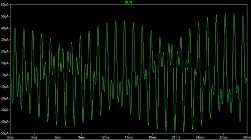
    Is this what phase conjugate electricity looks like in a scope?

    Originally posted by tswift View Post
    Good find! On a first reading, it appears to me as if the same principle is at work as in the Don Smith devices, the thing I've been trying to understand and generally calling "phase conjugate" electricity.

    ...snip
    Is this what phase conjugate electricity looks like in a scope?


    Generated by this simulation ...
    https://is.gd/phasecon

    ... within LTSpice?

    Leave a comment:


  • radioionics
    replied
    My is again plagiarized

    This patent plagiarizes my work. My patent clearly predates it...

    http://www.radio-ionics.com/pdf/US7800286.pdf

    -Bruce P.


    Originally posted by tswift View Post
    Good find! On a first reading, it appears to me as if the same principle is at work as in the Don Smith devices, the thing I've been trying to understand and generally calling "phase conjugate" electricity. The energy coming up from earth in response to a high voltage is characteristically different from normal electricity, and when you put it through a transformer interesting things happen. In the patent they use both natural atmospheric energy, and then give it a boost with a high voltage spark system. I think either natural or assisted the energy works the same way. This is essentially Don's demonstration of zapping the capacitor with the handheld Tesla coil all over again, and the collecting coil is between the capacitor and ground as I mentioned several posts back.

    I note they don't give any performance or power characteristics in the patent, it wouldn't surprise me if a system like this could generate kilowatts with minimal input. Also the coiled extendable ground radial system is quite interesting. Dragon, is this system at all similar to your own ground energy collector?

    Leave a comment:


  • dragon
    replied
    Originally posted by tswift View Post
    Actually that makes sense, I think I understand what you mean. Have you ever found that the earth current thus tapped seems to produce a power gain on going through a transformer?
    The energy that's there is free... so the question becomes, how can you take what's there and enhance it?

    Fig 3 in the patent shows the formation of a current loop on the lower windings - how would that affect the magnetic field in the transformer core? I'd say it raises current to it's maximum potential which increases the field in the core and is reflected on the output windings.

    From there it's a question of how much energy is needed to drive the impulse to bring the transformer into resonance.

    I found the patent interesting and quite informative in its simplistic form so I thought it would be of interest to others as well.

    Leave a comment:


  • ricards
    replied
    Originally posted by dragon View Post
    .. but we can tap that line with a lower resistance line and extract the current flow - a shared current flow. If you have a 100 amp flow on the line and you add a second line of equal resistance then you have 2 lines flowing 50 amps. Splitting the positive or negative as it were.

    The solenoid formula's use amp/turns to determine magnetic flux - voltage plays no part initially. A simple make 'n break circuit, solenoid, connected to the 2 grounds can create an active magnetic circuit. As long as the secondary line's (above ground) resistance is lower than the source line (ground) current will flow... large low resistance wire is the key.
    .
    So if one's circuit's resistance is like 1/10th of the earth's original resistance path.. you're like shunting the current into your circuit?.. interesting!

    is there a number or a constant telluric current rate? or is it largely fluctuating?

    on areas with Single wire earth return. would it be legal to do this?

    https://en.wikipedia.org/wiki/Single-wire_earth_return
    Last edited by ricards; 05-02-2017, 03:58 AM. Reason: add

    Leave a comment:


  • tswift
    replied
    Originally posted by dragon View Post
    Lets say you have a huge monster cable running through your yard that has hundreds of amps flowing through it. It spans the world, so in order to see a true potential difference you would need to have one probe in Mexico and the other in Canada. So when you stick 2 little "pins" in the ground with a small distance what is the best you can expect to see? Let's say we have a battery circuit, the battery represents the telluric source, the positive runs a few feet down the line and is connected to a load ( resistance) then back to the source. Our position is somewhere between the positive and load. If we tap 2 points on that line will we measure any voltage? Nope, nothing... at least not until you reach a point that resistance in the line causes a voltage difference.... but we can tap that line with a lower resistance line and extract the current flow - a shared current flow. If you have a 100 amp flow on the line and you add a second line of equal resistance then you have 2 lines flowing 50 amps. Splitting the positive or negative as it were.
    Actually that makes sense, I think I understand what you mean. Have you ever found that the earth current thus tapped seems to produce a power gain on going through a transformer?

    Leave a comment:


  • tswift
    replied
    Originally posted by Wistiti View Post
    Hi tswift,
    you could use ground plate for grounding

    https://ontario.nedco.ca/ground-rod-...B06154.hybris2

    it is much easy to burry them in your type of soil then drive a ground rod...
    Yes, or even an old radiator like Kapanadze! I might try it, we'll see. It would be easier if I had a backhoe....

    Leave a comment:


  • Wistiti
    replied
    Originally posted by tswift View Post
    In your experience, how important is low ground impedance to producing effects? I have been doing testing with two grounds, one the utility grid ground and one standard 8' ground rod I drove. I measured the resistance between them and was quite disheartened to get around 200 ohms (using the analog meter). I noticed some visible soil void around the one I installed, so I poured some water down it. This got it down to 100 ohms, which still doesn't sound very good. Unfortunately, I have soil with distinct limestone rock layers and driving a ground rod is an adventure. You might get lucky and have one that goes full depth, or you might be able to pound it through some thinner rocks, but if you hit a thick slab you're out of luck. I installed a really quality ground once by digging a foot-wide hole over six feet deep and backfilling it with sodium sulfate salt. This was a huge amount of work and I'm not anxious to repeat it if I can avoid it....
    Hi tswift,
    you could use ground plate for grounding

    https://ontario.nedco.ca/ground-rod-...B06154.hybris2

    it is much easy to burry them in your type of soil then drive a ground rod...

    Leave a comment:


  • dragon
    replied
    Originally posted by tswift View Post
    In your experience, how important is low ground impedance to producing effects? I have been doing testing with two grounds, one the utility grid ground and one standard 8' ground rod I drove. I measured the resistance between them and was quite disheartened to get around 200 ohms (using the analog meter). I noticed some visible soil void around the one I installed, so I poured some water down it. This got it down to 100 ohms, which still doesn't sound very good. Unfortunately, I have soil with distinct limestone rock layers and driving a ground rod is an adventure. You might get lucky and have one that goes full depth, or you might be able to pound it through some thinner rocks, but if you hit a thick slab you're out of luck. I installed a really quality ground once by digging a foot-wide hole over six feet deep and backfilling it with sodium sulfate salt. This was a huge amount of work and I'm not anxious to repeat it if I can avoid it....
    Having a high resistance between grounds might work to your advantage depending on the ground activity in your area. I would set up a battery and amp meter connected to your grounds to calculate the resistance, if there is some electrical activity the meters may not be accurate.

    Generally there is a large amount of amps flowing through the ground caused by a number of different activities, natural and man made. Basically the many different causes boil down to 2 basic mechanisms ... charge transmission or electromagnetic induction.

    Lets say you have a huge monster cable running through your yard that has hundreds of amps flowing through it. It spans the world, so in order to see a true potential difference you would need to have one probe in Mexico and the other in Canada. So when you stick 2 little "pins" in the ground with a small distance what is the best you can expect to see? Let's say we have a battery circuit, the battery represents the telluric source, the positive runs a few feet down the line and is connected to a load ( resistance) then back to the source. Our position is somewhere between the positive and load. If we tap 2 points on that line will we measure any voltage? Nope, nothing... at least not until you reach a point that resistance in the line causes a voltage difference.... but we can tap that line with a lower resistance line and extract the current flow - a shared current flow. If you have a 100 amp flow on the line and you add a second line of equal resistance then you have 2 lines flowing 50 amps. Splitting the positive or negative as it were.

    The solenoid formula's use amp/turns to determine magnetic flux - voltage plays no part initially. A simple make 'n break circuit, solenoid, connected to the 2 grounds can create an active magnetic circuit. As long as the secondary line's (above ground) resistance is lower than the source line (ground) current will flow... large low resistance wire is the key.

    Once you've established an active magnetic circuit you can manipulate voltage. Tesla's auto ignition 609250 and ozone 568177 patents are excellent example's of input boost circuits and more. Fig 3 of the above patent shows an interesting way of generating a substantial ground loop circuit.

    Leave a comment:

Working...
X