Announcement

Collapse
No announcement yet.

Donald Smith Devices too good to be true

Collapse
X
 
  • Filter
  • Time
  • Show
Clear All
new posts

  • @Dave45

    Yes I believe that the waves we send over a power line are far more dynamic
    then that. I think a more accurate description would be to say the wave rises a full 360 around the axis of the wire as it moves along the length of the wire.
    William Reed

    Comment


    • Originally posted by mr.clean View Post
      ...
      that is not the way i have it,
      if you are using the NST terminals for your pos and neg, there is no advantage to using the ground, cause the neg you are getting from your NST which is high voltage, which will run Out to lower V ground, (high pressure dissipating down to low pressure)
      the way i see it, rather than In up thru your ground wire, it will want to run out... thru the path of least resistance... which is usually the wire to ground, not the load

      you will however get a boost if you put the HV leads together, to get all the power the NST has, and put it all on one side of a cap, and attract a neg charge exclusively from the Earth

      HV terminals rectified and connected
      to one side of gap
      to one side of cap

      ground wire, to other side of gap
      to load
      to other side of cap
      I actually do have both terminals from the NST going through diodes to the positive side of my capacitor. What is a bit different in my setup is I am using a 12V NST, so it does not have a ground terminal, and the secondary is not center point grounded. I am using a bit of a trick to work around this. I do see the boost in power to the load when I connect in my ground, but I am also seeing the input current from my regulated DC supply increasing as well when I do this. This might be because of the difference in the way I am tying back ground to the NST. Since my secondary is not center tapped or center point grounded, I tie the ground return to one of the NST terminals. This gives me an unbalanced ground return however, whereas with yor NST which probably has a center point ground return on the secondary built in, your ground return to the NST should be balanced. That might be where the difference lies. I will see if I can post a schematic of my setup and some results of my testing in a while. Still doing a little more testing...
      level

      Comment


      • Originally posted by level View Post
        You can't use regular multimeters to accurately measure an AC waveform that is voltage spikes, and where the frequency is above 100 Hz or so. Also the readings on those type of AC socket plug in type wattmeters can be affected a lot by EM noise feeding back from the sparkgap. Also makes for unrealiable power measurements. Your input and output power measurements are likely not going to be very accurate at all. Your demo does demonstrate some interesting things though. Your 1 ohm power resistor, which I think is in series with the bulb, is getting quite hot so you obviously do have some half decent current flowing, and that would be expected when discharging a capacitor being charged to a high voltage, in pulses through a sparkgap. The high voltage capacitor discharge pulses (again, won't show on your multimeter ), should produce some big current spikes as well, which you have passing through the bulb. It is interesting that you observe the light getting a fair bit brighter when using your earth ground connection on the load, as this demonstrates that using earth ground is having some sort of effect on the load. Without proper measurements, we can't draw any definite conclusions about actual power increase, but there does appear to be a noticeble boost or change there of some degree. So, I think you have done a really good job in demonstrating that there could be a possible advantage of using a good earth ground when using these types of circuits to try to achieve over unity. However, your input and output power measurements that you have done in the video can't be relied on. Anyway, good demo of how using a good earth ground with this type of setup may possibly boost performance.

        P.S. I did some testing with a similar setup as you had in your video, and I see an increase in power supply current when I add the ground lead to the load.
        I also notice that adding the ground lead to the load causes the sparkgap firing pattern to change a bit. So, although I do see a boost in power to the load when the ground wire is connected, I am also seeing a corresponding increase in input current from my power supply. I may post some more details on my test results a bit later...


        Yes adding a ground to a resonant transformer will force a zero volt node
        at the ground connection, which will alter the wave structure on the coil.
        This can make a half wave coil into two quarter wave coils if the ground
        connection is in the center, from my observations it also lowers the resonant
        frequency of a single secondary when grounded. with no Earth connection
        there is no fulcrum from which to lever except the other end of the coil. The
        Earth connection alters the tuning of the coil ect. In most cases this results
        in a greater output and input.

        Try running any normal Tesla coil with no ground connection in quarter wave
        mode, how will you force a zero volt node at the correct place and keep it there ?

        Now ground connect the bottom of the Tesla coil and see what happens.

        Alternatively tune a continuous wave ground connected Tesla coil like kacher
        or Armstrong oscillator driven or even function generator driven, tune it to full
        resonant rise at 1/4 wave resonance. Then disconnect the ground connection
        and see what happens.

        Another way to see the effect is to use a balanced two transformer setup
        two Tesla coils transmitter and receiver connected by the secondary bottoms
        drive one in continuous wave mode and tune both to 1/4 wave resonance and
        look for the zero volts node, it should be somewhere between the two
        secondary bottoms, now disconnect the receiver and see what happens to
        the amplitude of the wave on the transmitter secondary and the input.

        When a ground connection is added it can very much increase and improve
        the resonant condition making the transformer more energetic and more stable
        in operation.

        This is not the best video but it shows that when the ground connection is
        made even between the two Tesla coil bottoms that both performance and
        input power were increased and the system was more stable because the
        zero volt node was forced to be fixed to the ground.

        This is not the best video, but it shows a pair of transformers with and
        without the center tap grounded. one is driven the other outputs to the motor.

        Idling Tesla Coils - YouTube

        A center tapped Half wave resonant coil will become two 1/4 wave coils when
        the center tap is ground connected. A 1/4 wave resonant transformer really
        needs it secondary base connected to a substantial ground or the Earth.

        It's kinda like half covering the air intake of an car engine to show the base
        performance then uncover it and let it get full air to simulate the act of
        connecting to the ground. The performance is improved because the base line
        performance is retarded.

        If I fired this setup up below without the secondary base grounded it,
        wouldn't work very well, sparks would issue forth from the secondary base to
        the primary because the potential at the bottom end of the secondary would
        swing about and go high and low, the tuning would be off and resonance
        would not be the best, this is the purpose of the grounding of a 1/4 wave
        coil. Believe it or not that transformer doesn't use a lot of power. sparking
        from the secondary to the primary would likely ruin my primary caps and stuff.
        It's a test of the charge holding capability of the toroid terminal, the best
        arcs at in the second half of the video. With enough power input the charge
        on the toroid terminal simply keeps increasing until it leaks off. Small leaks are
        noticed because of surge on start up. Full power was not used but I would
        imagine there would be around 200 to 300 Kv produced with no leak point.
        When an arc forms, successive discharges add to the arc length and so the
        arc length is not a measure of the voltage produced.

        Power level leak test - YouTube

        Cheers
        Last edited by Farmhand; 01-18-2013, 02:40 AM.

        Comment


        • Originally posted by Farmhand View Post
          Yes adding a ground to a resonant transformer will force a zero volt node
          at the ground connection, which will alter the wave structure on the coil.
          This can make a half wave coil into two quarter wave coils if the ground
          connection is in the center, from my observations it also lowers the resonant
          frequency of a single secondary when grounded. with no Earth connection
          there is no fulcrum from which to lever except the other end of the coil. The
          Earth connection alters the tuning of the coil ect. In most cases this results
          in a greater output and input.

          Try running any normal Tesla coil with no ground connection in quarter wave
          mode, how will you force a zero volt node at the correct place and keep it there ?

          Now ground connect the bottom of the Tesla coil and see what happens.

          Alternatively tune a continuous wave ground connected Tesla coil like kacher
          or Armstrong oscillator driven or even function generator driven, tune it to full
          resonant rise at 1/4 wave resonance. Then disconnect the ground connection
          and see what happens.

          Another way to see the effect is to use a balanced two transformer setup
          two Tesla coils transmitter and receiver connected by the secondary bottoms
          drive one in continuous wave mode and tune both to 1/4 wave resonance and
          look for the zero volts node, it should be somewhere between the two
          secondary bottoms, now disconnect the receiver and see what happens to
          the amplitude of the wave on the transmitter secondary and the input.

          When a ground connection is added it can very much increase and improve
          the resonant condition making the transformer more energetic and more stable
          in operation.

          This is not the best video but it shows that when the ground connection is
          made even between the two Tesla coil bottoms that both performance and
          input power were increased and the system was more stable because the
          zero volt node was forced to be fixed to the ground.

          This is not the best video, but it shows a pair of transformers with and
          without the center tap grounded. one is driven the other outputs to the motor.

          Idling Tesla Coils - YouTube

          A center tapped Half wave resonant coil will become two 1/4 wave coils when
          the center tap is ground connected. A 1/4 wave resonant transformer really
          needs it secondary base connected to a substantial ground or the Earth.

          It's kinda like half covering the air intake of an car engine to show the base
          performance then uncover it and let it get full air to simulate the act of
          connecting to the ground. The performance is improved because the base line
          performance is retarded.

          If I fired this setup up below without the secondary base grounded it,
          wouldn't work very well, sparks would issue forth from the secondary base to
          the primary because the potential at the bottom end of the secondary would
          swing about and go high and low, the tuning would be off and resonance
          would not be the best, this is the purpose of the grounding of a 1/4 wave
          coil. Believe it or not that transformer doesn't use a lot of power. sparking
          from the secondary to the primary would likely ruin my primary caps and stuff.
          It's a test of the charge holding capability of the toroid terminal, the best
          arcs at in the second half of the video. With enough power input the charge
          on the toroid terminal simply keeps increasing until it leaks off. Small leaks are
          noticed because of surge on start up. Full power was not used but I would
          imagine there would be around 200 to 300 Kv produced with no leak point.
          When an arc forms, successive discharges add to the arc length and so the
          arc length is not a measure of the voltage produced.

          Power level leak test - YouTube

          Cheers
          man you are basically there, put it this way, your circuits are elaborate enough to be inside Kapanadze's generator, and you have the knowledge of the operation of the whole picture
          (i keep refering to Kapanadze, but why not?)...

          it just seems like all you need to do is put some different things together in what may "possibly" look close to TK's layout, and make sense to you, i believe you will stumble on it!...
          assuming he's legit, which at this point, someone would have to prove him wrong,
          ... that could be the only way TK did it, right? working towards a vision, and stumbling on it?

          you understand the different effects of 1/4 and 1/2 wave better than i've heard from anyone, and also the quality of your work surpasses those i've seen with working TK replicas, so, you are so close man
          In the beginner's mind, there are many possibilities.
          In the expert's mind there are few.
          -Shunryu Suzuki

          Comment


          • Originally posted by Farmhand View Post
            ...
            It's kinda like half covering the air intake of an car engine to show the base
            performance then uncover it and let it get full air to simulate the act of
            connecting to the ground. The performance is improved because the base line
            performance is retarded.
            ...
            That might be the case, although I don't understand fully why connecting in the ground is giving me the results I am getting in my testing. I believe the way I tie in the ground in my test setup unbalances my secondary, but still not sure why it causes the NST to draw more current from the DC power supply, and also why more power is transfered to the load. It might well have to do with what you are saying, but I can't say I understand it at this point. Why do you suppose that grounding one side of the secondary causes the NST to draw more current to its primary, and more power is also delivered to the load? I will post a schematic of my test setup to see if anyone has any ideas why adding the ground wire does what it does.
            level

            Comment


            • Believe me when i say I am no expert, not by a long shot. My car example
              was not a good one, in reality the car would use more fuel when the air intake is choked.

              My thinking would be that when the ground is connected the secondary
              tuning becomes more stable and altered so the load can cause more of a
              phase shift or something like that. I was kind of referring to the center tapped
              Don Smith setup and or a regular Tesla coil or pair.

              To put it as simple as possible as I see it ( I hate to say that word simple I mean no offence) , connecting to ground is like adding
              some capacitance to the secondary, not only that but the capacitor plate is
              massive, this affects it's resonant frequency. This would alter the tuning
              relationship between the primary and secondary I guess.

              Edit to add: ( even though the Earth is massive the way it is connected the
              effective capacitance is small) I think.

              A similar effect can be had by using a large plate placed on the ground or just
              above it to form a capacitor with the Earth, then connect the ground
              connection from the secondary to the plate.

              Spark gaps compared to transistor driven brings another aspect into it as well.

              A multiple coils in resonance with load, caps and such is a daunting prospect.

              Mr Clean, I'll try to find the old drawing I made for the HV transfer to the
              inverting transformer, or I'll make a new drawing, please be patient. I don't
              claim this to be my idea (yet) someone may have already implemented it in
              some way. It might be difficult to draw so that it makes quick sense. I draw
              by hand, but I'm not an artist either. But I'll try.

              Cheers

              P.S. One thing I do sometimes is to use an aluminium plate under the coil base
              and then electrically connect that to the Earth as well as connect the coil to
              the plate, this in my thinking brings the Earth plane up to the coil and allows
              better interaction between the Earth plane and the elevated terminal of small
              low voltage Tesla coils when up on the bench.. Difficult to tell if there is much
              difference with so many influencing factors though.

              ..
              Last edited by Farmhand; 01-18-2013, 05:00 AM.

              Comment


              • Hi mr clean. I attached a drawing of the setup I used to test your setup with.
                I put a 0.47 ohm resistor in series with the negative lead on the power supply to monitor input current to the NST, and I used a 50 ohm resistor for the load. My regulated DC power supply has a built in digital voltmeter and ammeter, but the EM noise feeding back from the sparkgap makes the meter readings suspect.

                I had the supply output voltage set to 10VDC, and since the supply is well regulated I think that is a fairly reliable value for the supply voltage, but the input current reading on the digital meter may not have been very accurate at all. What I did was use a laser pointer IR thermometer to measure the temperature on R1 and R2 after about 4 minutes, and then I let the resistors cool off and then I connected the ground wire, and let it run for another 4 minutes and measured the temperature of the resistors again. The temperature on both the input current sensing resistor and the load resistor increased a fair bit with the ground wire connected, so input current definitely increased and power to the load increased as well with the ground wire connected. As I mentioned, my setup is probably a bit different than yours since I connect the ground to one of the NST secondary leads, which makes the secondary unbalanced with respect to ground. That may be what causes the input current to increase, although I don't understand why at this point. Maybe farmhand knows why this causes the input current to increase and output power delivered to the load to increase...

                The current reading from the digital power supply meter is probably not accurate.
                Ground wire not connected:
                Power Supply meters: 10V @ 1.27A
                R1 temp after 4 minutes: 94F
                R2 temp after 4 minutes: 240F

                Ground wire connected:
                Power Supply meters: 10V @ 1.95A
                R1 temp after 4 minutes: 142F
                R2 temp after 4 minutes: 315F

                A couple of interesting things I noticed when doing this test.
                Without the ground wire connected, the 50 ohm wire wound power resistor (which is basically a tiny coil with a lot of resistance) I was using for the load rings just like a coil with each pulse from the cap discharge. With the ground wire connected to the bottom of the resistor, there is no ringing. At least I think it is the power resistor that is causing the ringing.

                The temperature on the power resistors is not even across the power resistors. For example when the power resistor was 315F, it was hottest at the end of the resistor connected to the capacitor and only about 90F at the end of the resistor connected to ground. I noticed the exact same temperature gradient on the 0.47 ohm current sensing resistor as well. It was a lot cooler on the end that connected to the negative terminal on the power supply, and the end that went to the NST was the hotter end. I measured my temperatures at the hot end of the power resistors.
                P.S. I did further testing with this and I determined that the apparent temperature gradient I was seeing across the power resistors is actually due to a quirk with the way the IR thermometer reads temperatures. Also, I guess with the small surface of the power resistor and the thermometer held in fairly close that the laser dot sighting feature is off somewhat. For this type of measurement you just have to move the thermometer around until you get the highest reading, and then you know are lined up directly at the power resistor. Since I took my temperature measurements on the power resistrs where I was reading the highest temperature, the measurements should be fairly accurate, I would guess.

                Last edited by level; 04-05-2016, 11:09 PM.
                level

                Comment


                • Originally posted by Farmhand View Post
                  ...
                  My thinking would be that when the ground is connected the secondary
                  tuning becomes more stable and altered so the load can cause more of a
                  phase shift or something like that. I was kind of referring to the center tapped
                  Don Smith setup and or a regular Tesla coil or pair.

                  To put it as simple as possible as I see it ( I hate to say that word simple I mean no offence) , connecting to ground is like adding
                  some capacitance to the secondary, not only that but the capacitor plate is
                  massive, this affects it's resonant frequency. This would alter the tuning
                  relationship between the primary and secondary I guess.
                  ...
                  Yes, it could be that the resonant frequency of the NST transformer is being altered when the ground is connected to one side. I will try to do some tests to see if I can determine if the frequency of the NST is changing when I connect the ground. Not sure if NST's are designed to run in resonance or not though. Thanks for the feedback, and by the way you are quite the tesla coil wizard. Really nice stuff.... Now I know who to ask about tesla coil design questions...

                  level

                  Comment


                  • Actually this might be a better way to add an earth ground to a 12VDC NST sparkgap driver circuit, but I don't have two more HV diodes to try it to see if using a full wave bridge rectifier gives any improvement.
                    Last edited by level; 04-05-2016, 11:09 PM.
                    level

                    Comment


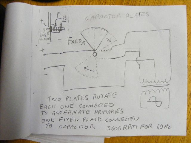
                    • The idea is kind of like this, the plates would be all 1/4 circle segments, one
                      plate fixed and connected to the HV, two other plates opposite each other and
                      insulated form each other and connected to the primary windings of the
                      transformer by slip rings or such other way so that they can be spun in close
                      proximity to the fixed and charged capacitor plate, as the rotating plates passed
                      the capacitance sould increase to maximum then decline to nil when the next
                      one begins it's pass. There could be variations, maybe there could be two fixed
                      plates one positive and one negative. But the theory would be that energy
                      would be transferred to the rotating plates as they passed the fixed charged
                      plate and this could be stepped down and transformed to AC by the transformer. The plate spacing would depend on voltage.
                      This maybe not scaleable to 60 Hz. Just an idea. And by design very
                      dangerous, almost a rotary guillotine.

                      I would actually like to try this in small scale at high speed, but a certain
                      amount of engineering is involved and commitment.

                      This is my old drawing, it's a bit rough.


                      Level, I'm flattered, I think I have a "feel" for it but I'm not very technical, I
                      struggle with the numbers. I'ts nice to be able to connect up the big coil and
                      show people who haven't seen such things before.

                      Oh the coals and ash around the ground stake I used just because I thought
                      it might improve things.

                      Cheers

                      Comment


                      • Originally posted by Farmhand View Post
                        The idea is kind of like this, ...
                        Very cool. Yeah, building it would take some careful planning and likely a fair bit of work and maybe some trial and error as well...
                        level

                        Comment


                        • Originally posted by level View Post
                          I actually do have both terminals from the NST going through diodes to the positive side of my capacitor. What is a bit different in my setup is I am using a 12V NST, so it does not have a ground terminal, and the secondary is not center point grounded. I am using a bit of a trick to work around this. I do see the boost in power to the load when I connect in my ground, but I am also seeing the input current from my regulated DC supply increasing as well when I do this. This might be because of the difference in the way I am tying back ground to the NST. Since my secondary is not center tapped or center point grounded, I tie the ground return to one of the NST terminals. This gives me an unbalanced ground return however, whereas with yor NST which probably has a center point ground return on the secondary built in, your ground return to the NST should be balanced. That might be where the difference lies. I will see if I can post a schematic of my setup and some results of my testing in a while. Still doing a little more testing...
                          yeah that prob would make a difference, i have tried several HV drivers,
                          (with the exception of the ones i REALLY intend to use cause they are being repaired)
                          ...and not all work the same at identical voltages, that can be a maker or breaker
                          i wouldnt be able to guarantee your results unless similar components were used, but it should work someway with a single ended transformer
                          In the beginner's mind, there are many possibilities.
                          In the expert's mind there are few.
                          -Shunryu Suzuki

                          Comment


                          • Originally posted by rosehillworks View Post
                            @mr.clean

                            I am enjoying everything you have been showing here
                            I think you will enjoy this so please take a look AT&T Archives: Similiarities of Wave Behavior (Bonus Edition) - YouTube
                            hey that was sweet, i love seeing these vids thanks
                            In the beginner's mind, there are many possibilities.
                            In the expert's mind there are few.
                            -Shunryu Suzuki

                            Comment


                            • Originally posted by Farmhand View Post
                              The idea is kind of like this, the plates would be all 1/4 circle segments, one
                              plate fixed and connected to the HV, two other plates opposite each other and
                              insulated form each other and connected to the primary windings of the
                              transformer by slip rings or such other way so that they can be spun in close
                              proximity to the fixed and charged capacitor plate, as the rotating plates passed
                              the capacitance sould increase to maximum then decline to nil when the next
                              one begins it's pass. There could be variations, maybe there could be two fixed
                              plates one positive and one negative. But the theory would be that energy
                              would be transferred to the rotating plates as they passed the fixed charged
                              plate and this could be stepped down and transformed to AC by the transformer. The plate spacing would depend on voltage.
                              This maybe not scaleable to 60 Hz. Just an idea. And by design very
                              dangerous, almost a rotary guillotine.

                              I would actually like to try this in small scale at high speed, but a certain
                              amount of engineering is involved and commitment.

                              This is my old drawing, it's a bit rough.


                              Level, I'm flattered, I think I have a "feel" for it but I'm not very technical, I
                              struggle with the numbers. I'ts nice to be able to connect up the big coil and
                              show people who haven't seen such things before.

                              Oh the coals and ash around the ground stake I used just because I thought
                              it might improve things.

                              Cheers
                              sweet ideas, looks good to me!
                              In the beginner's mind, there are many possibilities.
                              In the expert's mind there are few.
                              -Shunryu Suzuki

                              Comment


                              • Originally posted by level View Post
                                Hi mr clean. I attached a drawing of the setup I used to test your setup with.
                                I put a 0.47 ohm resistor in series with the negative lead on the power supply to monitor input current to the NST, and I used a 50 ohm resistor for the load. My regulated DC power supply has a built in digital voltmeter and ammeter, but the EM noise feeding back from the sparkgap makes the meter readings suspect.

                                I had the supply output voltage set to 10VDC, and since the supply is well regulated I think that is a fairly reliable value for the supply voltage, but the input current reading on the digital meter may not have been very accurate at all. What I did was use a laser pointer IR thermometer to measure the temperature on R1 and R2 after about 4 minutes, and then I let the resistors cool off and then I connected the ground wire, and let it run for another 4 minutes and measured the temperature of the resistors again. The temperature on both the input current sensing resistor and the load resistor increased a fair bit with the ground wire connected, so input current definitely increased and power to the load increased as well with the ground wire connected. As I mentioned, my setup is probably a bit different than yours since I connect the ground to one of the NST secondary leads, which makes the secondary unbalanced with respect to ground. That may be what causes the input current to increase, although I don't understand why at this point. Maybe farmhand knows why this causes the input current to increase and output power delivered to the load to increase...

                                The current reading from the digital power supply meter is probably not accurate.
                                Ground wire not connected:
                                Power Supply meters: 10V @ 1.27A
                                R1 temp after 4 minutes: 94F
                                R2 temp after 4 minutes: 240F

                                Ground wire connected:
                                Power Supply meters: 10V @ 1.95A
                                R1 temp after 4 minutes: 142F
                                R2 temp after 4 minutes: 315F

                                A couple of interesting things I noticed when doing this test.
                                Without the ground wire connected, the 50 ohm wire wound power resistor (which is basically a tiny coil with a lot of resistance) I was using for the load rings just like a coil with each pulse from the cap discharge. With the ground wire connected to the bottom of the resistor, there is no ringing. At least I think it is the power resistor that is causing the ringing.

                                The temperature on the power resistors is not even across the power resistors. For example when the power resistor was 315F, it was hottest at the end of the resistor connected to the capacitor and only about 90F at the end of the resistor connected to ground. I noticed the exact same temperature gradient on the 0.47 ohm current sensing resistor as well. It was a lot cooler on the end that connected to the negative terminal on the power supply, and the end that went to the NST was the hotter end. I measured my temperatures at the hot end of the power resistors.

                                hehe positive and negative... hot and cold... amps and volts...

                                hot and cold collide in the sky, and Millions of watts thunders down from a cloud

                                ive noticed the same thing, its hot on the one positive side and cold on the negative side, the bulb and resistor are raging hot tho, im not sure where the hot and cold start and stop,
                                but you just said the Load resistor was cold on one end?

                                that basically by definition proves that it really is Coming to the load from the ground to feed half the load! not just positive thru all

                                great work man! i love the ground transfer switch maybe a single throw switch to disconnect the neg of fwbr, while at same time connecting to ground? if any advantage
                                Last edited by mr.clean; 01-18-2013, 05:32 PM.
                                In the beginner's mind, there are many possibilities.
                                In the expert's mind there are few.
                                -Shunryu Suzuki

                                Comment

                                Working...
                                X