Announcement

Collapse
No announcement yet.

Donald Smith Devices too good to be true

Collapse
X
 
  • Filter
  • Time
  • Show
Clear All
new posts

  • Originally posted by Blue_Serge View Post
    Hello,

    Here is a short video (Link: Test 1.mp4 - YouTube) of my actual setup and the same circuit I posted earlier. The first part of the video I show you the system and in the second part I show you the signal picked up on a probe left just beside the L2 coil.
    Not bad

    Questions:
    1) How much power your NST consumes to power 100W bulb?
    2) Do you use AV HV diode plug to charge capacitor before spark gap?
    3) Your oscilloscope shows deceasing self oscillations. Did you try to reach resonance and reverse it to increasing self oscillations?
    Attached Files
    Last edited by T-1000; 11-27-2011, 12:30 PM.

    Comment


    • Originally posted by Blue_Serge View Post
      Hello,

      Thank you Zilino for your advice. I will try your suggestions next.

      The input power for the NST is 240 watts. (120V * 2Amps)

      This system is still far from overunity, however it is a step in the right direction. I will try the this again with a third coil and see if that makes any difference. I'll keep you guys posted. Thanks.
      Hi Blue_Serge,
      did you measure the 120V/2A or is that the value from the label of your NST?
      You must not multiply the values from the labels. Usually they are max. values and are not true at same time. This notion applies to the input and output figures as well.
      Think of a water pump. With colsed output tap it supplies a certain pressure. As soon as you open the tap the max. pressure will decrease, while the water flow will increase starting from zero. When maximum water flow - you have the lowest pressure.
      @all: if you share figures of voltage / amps of your NSTs please add if they are measured or extracted fom the label. This will help to prevent confusions.
      rgds John
      Experts spend hours a day in order to question their doing while others stopped thinking feeling they were professionals.

      Comment


      • Originally posted by JohnStone View Post
        Hi Blue_Serge,
        Think of a water pump. With colsed output tap it supplies a certain pressure. As soon as you open the tap the max. pressure will decrease, while the water flow will increase starting from zero. When maximum water flow - you have the lowest pressure.
        John
        Well,...not exactly, I think you mean a compressor (positive displacement pump) and not a water (centrifugal) pump. Water pressure, in a closed loop system, is dictated by the amount of water in the system (static head). Closing the head on the pump results in no change in system pressure. Of course a large pump will quickly damage itself.

        If you have a hot water boiler in your house you will notice that the pressure gauge stays at around 12 psig (one familly house) with the pump on and off.

        -Core
        Last edited by Core; 11-27-2011, 07:15 PM.

        Comment


        • A simple recommendation that works for input.

          Power your device thru a Killowatt meter!!

          I am also trying to do a simple resistor in water for "Butch Calorimetry"
          on the load end!!

          We need to get this figured

          Chet
          If you want to Change the world
          BE that change !!

          Comment


          • NST input power

            Hello,

            I measured the input power with an Amp meter connected in series on the input side. I don't have a kilowatt meter but I will look into getting one.

            Zilano made some suggestions earlier and I wanted to try them out next. I was thinking of making the third coil either a bifilar or caduceus coil and attaching the right capacitor to resonant with the pick up coils. Which is better a bifilar or Caduceus coil?

            @T-1000: I used 2 HV 10KV - 30mA diodes to charge the primary capacitor then discharge it through the spark gap into L1 or primary coil. I was just showing the signal that is picked up by the probe. From what I understand I believe I need a signal that is rising in voltage or ringing up, no?
            Last edited by Blue_Serge; 11-27-2011, 07:50 PM.

            Comment


            • Originally posted by Core View Post
              Well,...not exactly, I think you mean a compressor (positive displacement pump) and not a water (centrifugal) pump. Water pressure, in a closed loop system, is dictated by the amount of water in the system (static head). Closing the head on the pump results in no change in system pressure. Of course a large pump will quickly damage itself.

              If you have a hot water boiler in your house you will notice that the pressure gauge stays at around 12 psig (one familly house) with the pump on and off.

              -Core
              You are right. I should have discribed it more precisely. I had a simple centrifugal garden pump in my mind as open system.
              rgds John
              Experts spend hours a day in order to question their doing while others stopped thinking feeling they were professionals.

              Comment


              • Hi Blue-Serge,
                the community will appreciate it very much if you could post a schematic of the exact connections. Further modifications will be easier to track and discuss.
                rgds John
                Experts spend hours a day in order to question their doing while others stopped thinking feeling they were professionals.

                Comment


                • Originally posted by Blue_Serge View Post
                  Hello,
                  @T-1000: I used 2 HV 10KV - 30mA diodes to charge the primary capacitor then discharge it through the spark gap into L1 or primary coil. I was just showing the signal that is picked up by the probe. From what I understand I believe I need a signal that is rising in voltage or ringing up, no?
                  Youp, you need ringing up signal. I attached our setup pdf as example.
                  Another important part is to have NST ringing too. So you can feed 1 wire electricity into AV (Avramenko) diode plug what charge capacitor before spark gap.
                  Just querious, if you put voltmeter and ampermeter before your setup and show what power it consumes, that would answer to question "power in and power out?"..
                  Please see Avramenko's Free Electrons Pump v1.0 by Jean-Louis Naudin as example of its usage.

                  Comment


                  • @JohnStone

                    Here is the circuit I used and demonstrated in the video.

                    @T-1000
                    Thanks for the suggestion. I'll work towards getting a ringing up wave pattern.
                    If you are asking what the input power and out power on my system, the system input is 240W and output I don't yet. I use for now a 100W bulb to see if there is work being done.
                    Attached Files

                    Comment


                    • zilano -

                      the circuit with MOV in it , what is a MOV ? and how do you get LV 350v ?? dc OR AC ?

                      Comment


                      • Originally posted by hello_all View Post
                        zilano -

                        the circuit with MOV in it , what is a MOV ? and how do you get LV 350v ?? dc OR AC ?
                        Hi,
                        MOV (wikipedia) is a metal oxide varistor. This is a special kind of avery fast overvoltage protection (zehners are too lazy). In this schematic any overvoltage spike can fire the flash tube out of the inteded frequency by 2KV pulses. Therefore the MOV.
                        rgds John
                        Last edited by JohnStone; 11-28-2011, 05:14 PM.
                        Experts spend hours a day in order to question their doing while others stopped thinking feeling they were professionals.

                        Comment


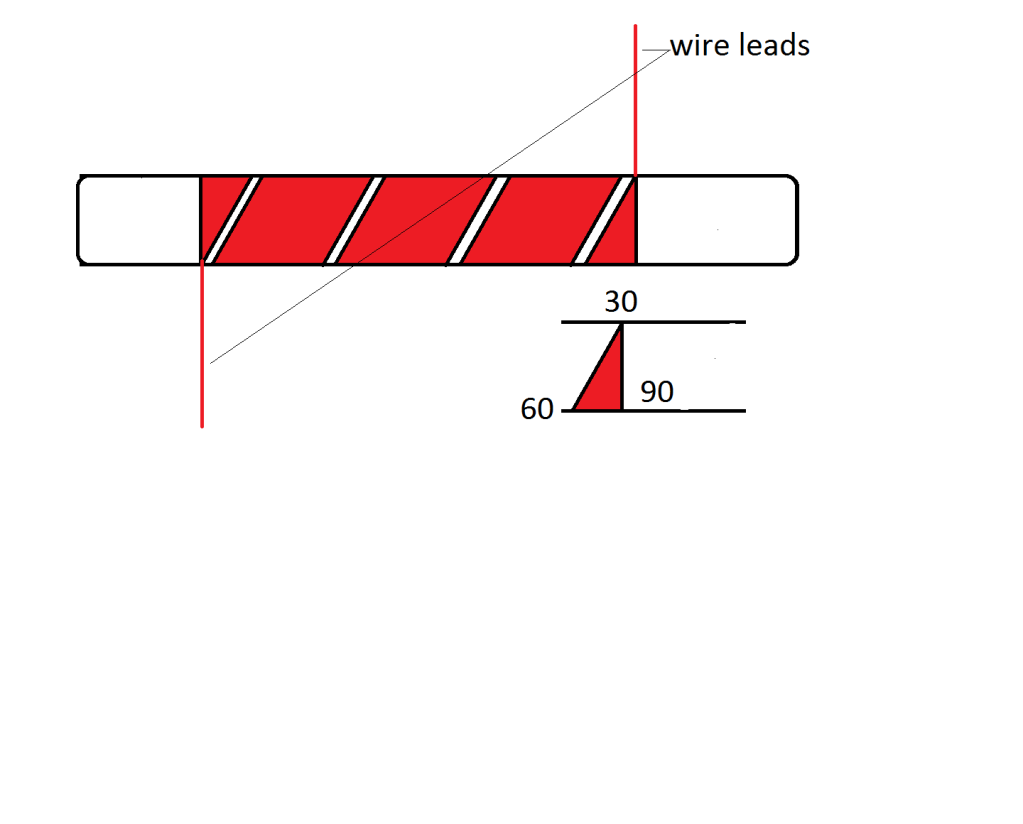
                        • Make your L2 coils like this, out of ribbon conductor the angle should be 51.83


                          http://www.energeticforum.com/renewa...tml#post169018
                          Half of the Answer is knowing the right Question

                          Comment


                          • Originally posted by zilano
                            use this in ur current version if u dont intend to use third coil. short/shunt the ccw coil in secondary.

                            rgds
                            zzzz
                            Hi Zilano,
                            thanks for this clear hint! Most of your hints correspond exactly to the Vladimir Utkin paper. That is good news. But the Utkin paper is very sparse with explanations for mere mortals and greenhorns like me. So please keep teching us! Thanks for your commitment!
                            rgds John
                            Experts spend hours a day in order to question their doing while others stopped thinking feeling they were professionals.

                            Comment


                            • Spark generation

                              Hi all,
                              studying a bunch of very differnt schematics I am often confused by the method of the spark generation - mostly not explained. There is a big range out there from brute force energy waste to very smooth high frequency sparks. Sad to see a lot of vids with unfortunate spark generation. I vote the spark type to be essential and therefore I'd like to share my first notions. Please consult the attachment:

                              Tests were performed with a simple L1 coil (100mm air core / 55 turns).
                              Direct self triggerd sparks (schematics A1-A5)
                              These are self triggering sparks generated directly from the half or full wave rectified signal.
                              Mains frequency (sine / schematic A1-A3):
                              These sparks do not like to occure regularly. Especially if the output is sine from mains (A1-A3). The best behavior was when the voltage was reduced to minimum while the sparks still trigger. As the spark ends at zero crossing the duration is quite long and surprisingly the L1 coil does not oscillate. It oscillates if sparks are of short duration only. At longer timed sparks there is one cycle only and no L1 oscillation. Tesla coilers state that this is because the energy is being reflected back and at just that time the spark stops.
                              At fw rectifier and brute force spark sometimes the spark burns continuously like a welder. This is because the short time of zero crossing is too short in order the plasma to discharge. Such a spark does make no sense apart from fun for pyrotechnic hobbyists.

                              Medium frequency NST (ca. 40 KHz/ schematic A4,A5)
                              I had no NST of this type available but tested different CCFL PSU. The behavior is better but still no regular triggering.

                              Spark from preloaded capacitor (schematic B1)
                              - Small capacitor added at previous schematics. Before this action the sparks started with a tired glow discharge and there is no pep in it. With added (small) capacitor it discharges instantly and without that glow before and this is what we expect it to do.
                              Needless to mention that not every coiled capacitor is able to dischasrge abruptly - but this is essential. (low ESR required)
                              - At A type schematics above the output from the HV PSU was unloaded (high impedance) before every spark and I assume that the high impedance causes undefined voltage spikes and this causes very unregular sparks. The capacitor C is now a defined load and any spike will be absorbed by the capacitor prior the trigger time.
                              - The capacitor needs to be tuned thoroughly. Too small values do not overcome the glow discharge while too big capacitors do not charge fast enough. If they discharge - there is often this "one cycle behavior" referred above. It is suffitient if the capacitor charges during one single pulse up to the spark event.
                              - I got nice oscilaltions with 100pF and 2 KV. At Mains frequency the repetition is too rarely. With 40 KHz the next pulse occures before the oscillation stopped. I got similar oscillation like Blue_Serge some posts ago.

                              Sparks triggerd externaly (schematics C1,2)
                              I admit that I did test this yet with mains only.
                              The basic idea is to have a smooth DC HV voltage and trigger the spark (usually a flash tube) at predefined time.
                              - If the HV source is of low (like foto flash light) power the flash discharges the capacitor, stops and the sequence can start after recharge and trigger again.
                              - If the HV source is of suffitient power the spark (flash tube) does not stop and we have a welder. (see above). In this case a series resistor or coil is inserted and a second capacitor (C2) to GND (see schematic C1). The capacitor C2 determines the flash energy and the Resistor (coil) prevents a too high current in order the spark can stop.
                              - Please regard the C2 schematic - Zilano style. This is waht I will test next in order to unterstand it's behavior. This is a mix between B1 and C1. The inductance replaces the resistor from C1.

                              Spark triggered by resonance (D)
                              This is still a secret to me. (therefore no schematic). The basic idea is that at every single oscillation amplitude a corresponding spark adds additional energy (increasing oscillations). These sparks need to be tuned well and brute force is a no go.
                              No idea how some sparks of mains frequency can do this requested behavior. Same at 40 KHz like blue serge. Maybe I'm wrong.
                              Aniway - from the Utkin paper I learned that there are some different "mechnics" producing OU and the OU behavior can be introduced at different points in the schematic - and they can be combined as well. I urge you to study Utkin and diskuss & share. I feel it to be essential to discern the different "mechanics" and address them clearly in the schematics.

                              Further studies planned
                              - Zilano style spark (see C2)
                              - Manufactoring of some coils (somehow standardized similar to LEGOkit - cw,ccw, bifilar ...) proposed by Zilano and Utkin and study and test of their behavior and interaction.
                              rgds John
                              Last edited by JohnStone; 01-11-2013, 10:09 PM.
                              Experts spend hours a day in order to question their doing while others stopped thinking feeling they were professionals.

                              Comment


                              • Originally posted by Dave45 View Post
                                Make your L2 coils like this, out of ribbon conductor the angle should be 51.83


                                http://www.energeticforum.com/renewa...tml#post169018
                                Hi Dave45,
                                please explain in detail.
                                - Are all ends of the ribbon tied together?
                                - I did not find a relation to the mentioned thread. What special effect expected?
                                rgds John
                                Last edited by JohnStone; 11-28-2011, 08:01 PM.
                                Experts spend hours a day in order to question their doing while others stopped thinking feeling they were professionals.

                                Comment

                                Working...
                                X